INSTALLING THE XTRA LINK 284M DUAL IR EMITTER
Plug the 284M Dual IR Emitter into the jack marked "EMITTER" on the CPL77 Coupler in the Main Room.
The 284M emitters should be installed directly to the infrared sensor "window" on the front panel of the satellite receiver, VCR, cable box, etc. Simply remove the paper backing exposing the adhesive surface of each emitter and apply them to the center of the sensor window.
NOTE: Although the 284M appears dark to the eye, it is transparent to infrared. Positioning the 284M directly over the infrared window(s) of the component(s) will not block direct IR control from a handheld remote.
OPERATION
To use the Xtra Link Remote Control Extension System, simply point your handheld remote control(s) at the
NOTE: The maximum usable distance between your IR remote and the
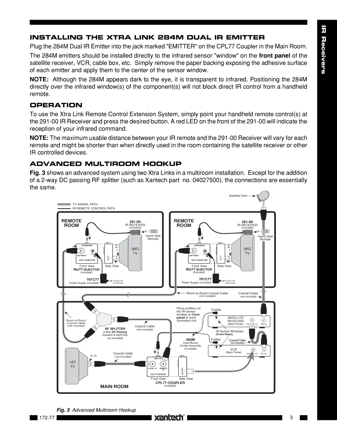
ADVANCED MULTIROOM HOOKUP
Fig. 3 shows an advanced system using two Xtra Links in a multiroom installation. Except for the addition of a 2-way DC passing RF splitter (such as Xantech part no. 04027500), the connections are essentially the same.
Satellite Dish ![]()
![]()
TV SIGNAL PATH
IR REMOTE CONTROL PATH
IR Receivers
REMOTE
ROOM
IR RECEIVER
+12 V
ANT INPUT
INJ77 INJECTOR
Front View
INJ77 INJECTOR
(included)
781C77
Power Supply (included)
IR RECEIVER
(included)
Hand Held
Remote
RF
IN
2ND
TV
TO TV![]()
![]()
![]()
Side View
![]()
![]()
![]()
![]() To 220 V AC (unswitched)
To 220 V AC (unswitched)
REMOTE
ROOM
IR RECEIVER
+12 V
ANT INPUT
INJ77 INJECTOR
Front View
INJ77 INJECTOR
(included)
781C77
Power Supply (included)
IR RECEIVER
(included)
Hand Held
Remote
RF
IN
3RD
TV
TO TV![]()
![]()
![]()
Side View
![]()
![]()
![]()
![]() To 220 V AC (unswitched)
To 220 V AC (unswitched)
Coaxial Cable | |
(not included) | (not included) |
Coaxial Cable
(not included)
| RF SPLITTER | Coaxial Cable |
| (not included) | |
|
| |
| (Xantech # 04027500, |
|
| not Included) |
|
RF IN | Coaxial Cable |
|
(not included) |
|
EMITTER
Place emitters on | Emitter |
|
|
the IR sensor |
|
| |
|
|
| |
window on front |
|
|
|
panel of each |
| SATELLITE |
|
controlled unit. |
| RECEIVER |
|
|
| (Back Panel) OUT TO TV | RF IN |
| IR Sensor Windows |
| |
| (Front Panel) |
| |
284M | Emitter | Coaxial Cable |
|
Dual Mouse |
| (not included) |
|
Emitter Assembly |
|
|
|
(included) |
| VCR |
|
|
| (Back Panel) | RF IN |
|
| OUT TO TV | |
1ST
TV
LOCAL TV REMOTE
TV
CPL77 COUPLER
SAT/VCR |
Front ViewSide View
CPL77 COUPLER
MAIN ROOM | (included) |
|
|
| Fig. 3 | Advanced Multiroom Hookup |
|
|
| |
|
|
|
| |
|
|
|
|
|
|
|
| 3 |
| |
|
|
|
|
| |||
|
|
|
|
|
|
|
|
|
|
|
|
|
|
|
|