Satellite Dish | TV SIGNAL PATH | |
IR REMOTE CONTROL PATH | ||
|
INJ94 INJECTOR | INJ94 INJECTOR | ||||
RECEIVER | RECEIVER | ||||
(included) | (included) | (included) | (included) | ||
|
|
|
|
| |
| TV | INPUT | Hand Held | TV | INPUT |
Hand Held | INJ94 INJECTOR | INJ94 INJECTOR | |||
Remote | IR |
| Remote | IR |
|
| +12 V |
| +12 V | ||
| RCVR |
| RCVR | ||
2ND |
|
| 3RD |
|
|
TV |
| Coaxial Cable | TV | Coaxial Cable | |
| RF IN | (included) |
| RF IN | (included) |
|
|
|
| ||
|
|
|
| ||
|
| Power Supply (included) |
| Power Supply (included) | |
REMOTE ROOM | 120 V AC | REMOTE ROOM | 120 V AC | ||
(unswitched) | (unswitched) | ||||
|
| ||||
| Coaxial Cable |
|
|
|
| ||
| (not included) |
|
|
|
|
| (not included) |
|
| Emitter | Place emitters on | Coaxial Cable |
| OUT | OUT |
|
|
| the IR sensor |
| |||
| SATELLITE |
| window on front | (included | CPL94B COUPLER | I N | |
|
| panel of each | with |
| |||
| OUT TO TV RECEIVER |
|
| (included with |
| ||
RF IN |
| controlled unit |
|
| |||
|
|
|
|
| |||
| (Back Panel) |
| (see text). |
| SAT/VCR | REMOTE TV | |
|
|
|
|
| |||
| IR Sensor Windows |
|
| CPL94B COUPLER | RF SPLITTER | ||
| 282M & |
| EMITTER | EMITTER | |||
| (Front Panel) |
| |||||
| 283M |
|
|
| (not Included) | ||
| Coaxial Cable | Emitter |
|
|
| ||
| IR Emitters |
|
|
|
| ||
| (not included) |
| (included |
|
| Coaxial Cable | |
| VCR |
| with |
|
| (included with | |
|
|
| OUT |
|
|
| |
RF IN OUT TO TV (Back Panel)
I N
OUT
RF SPLITTER |
|
|
|
| |
(not included) | RF IN | 1ST |
| TV | |
Coaxial Cable |
| |
|
| |
(not included) |
|
|
| Coaxial Cable |
|
| (not included) |
|
MAIN ROOM
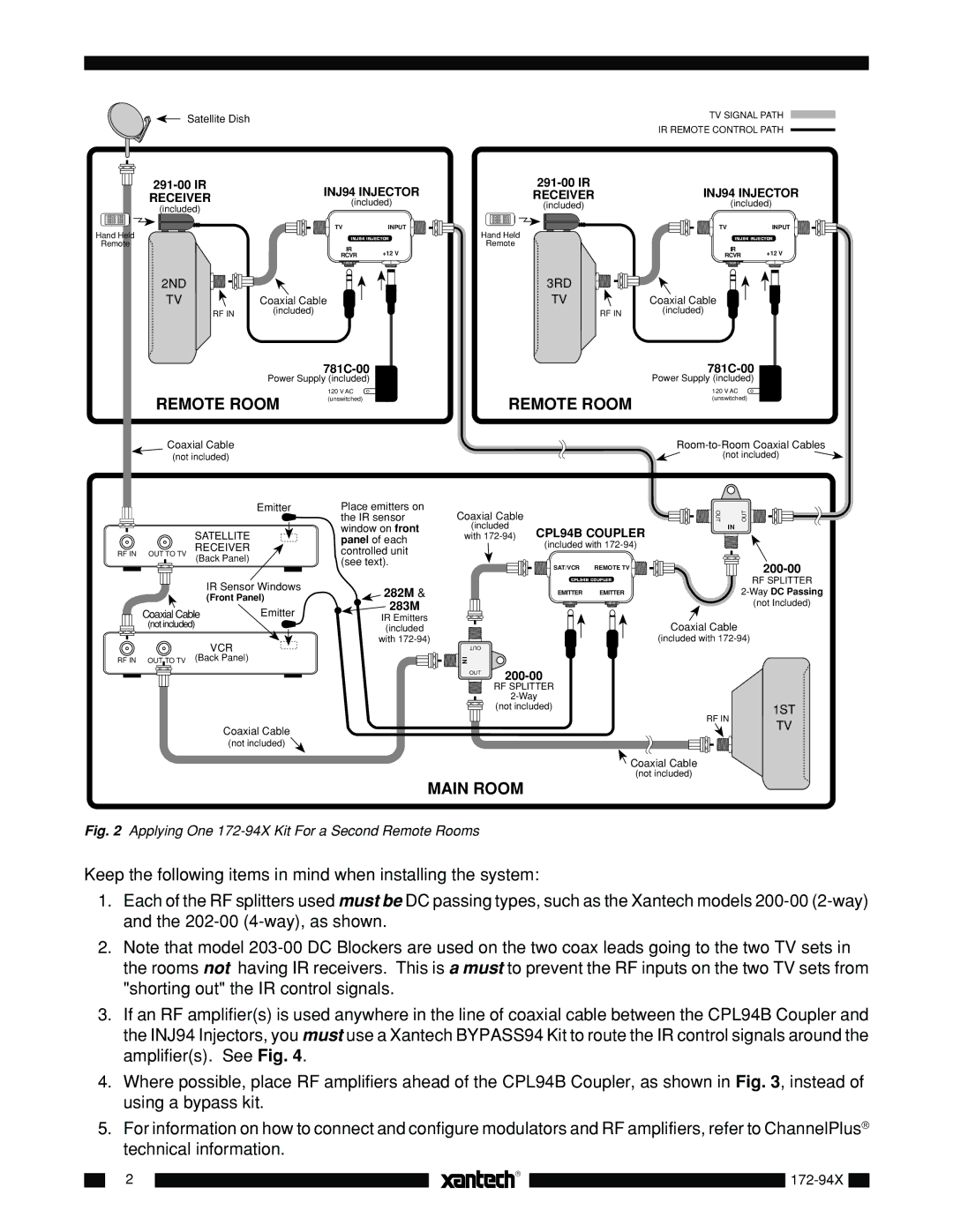
Fig. 2 Applying One 172-94X Kit For a Second Remote Rooms
Keep the following items in mind when installing the system:
1.Each of the RF splitters used must be DC passing types, such as the Xantech models
2.Note that model
3.If an RF amplifier(s) is used anywhere in the line of coaxial cable between the CPL94B Coupler and the INJ94 Injectors, you must use a Xantech BYPASS94 Kit to route the IR control signals around the amplifier(s). See Fig. 4.
4.Where possible, place RF amplifiers ahead of the CPL94B Coupler, as shown in Fig. 3, instead of using a bypass kit.
5.For information on how to connect and configure modulators and RF amplifiers, refer to ChannelPlus® technical information.
|
|
|
2 |
| |
| ||
|
| |
|
|
|
|
|
|