INSTALLATION INSTRUCTIONS
172-94X
XTRA LINK 2®
REMOTE CONTROL EXPANSION KIT
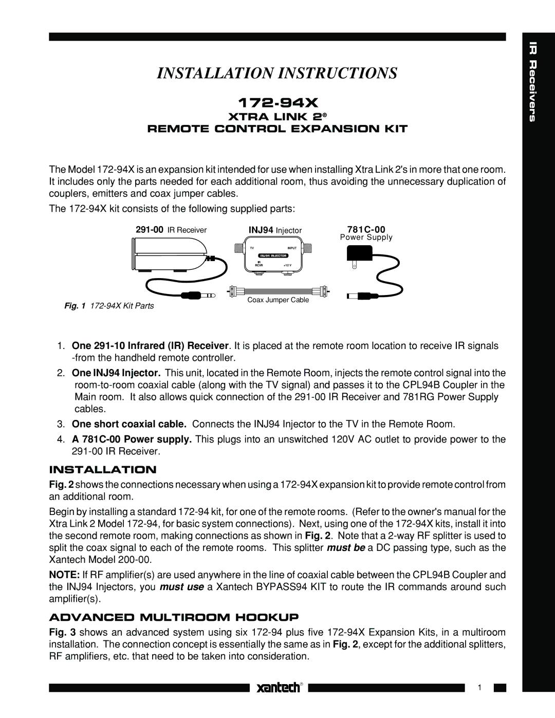
The Model
The
INJ94 Injector | ||
|
| Power Supply |
TV | INPUT |
INJ94 INJECTOR | |
IR | +12 V |
RCVR | |
Coax Jumper Cable
Fig. 1 172-94X Kit Parts
1.One
2.One INJ94 Injector. This unit, located in the Remote Room, injects the remote control signal into the
3.One short coaxial cable. Connects the INJ94 Injector to the TV in the Remote Room.
4.A
INSTALLATION
Fig. 2 shows the connections necessary when using a 172-94X expansion kit to provide remote control from an additional room.
Begin by installing a standard
NOTE: If RF amplifier(s) are used anywhere in the line of coaxial cable between the CPL94B Coupler and the INJ94 Injectors, you must use a Xantech BYPASS94 KIT to route the IR commands around such amplifier(s).
ADVANCED MULTIROOM HOOKUP
Fig. 3 shows an advanced system using six 172-94 plus five 172-94X Expansion Kits, in a multiroom installation. The connection concept is essentially the same as in Fig. 2, except for the additional splitters, RF amplifiers, etc. that need to be taken into consideration.
1
