CONTROLLED COMPONENTS
Satellite Receiver
| 282M |
VCR | or |
| 283M |
Laser Disc | Mouse |
| Emitters |
CD Changer
Power
Supply
To 120 V AC (unswitched)
CC62
Remote Relay Module
CC62
REMOTE RELAY MODULE
| IR CONFIRM |
IR IN | GND GND +12V |
12 VDC
1A
+12V DC
RELAY | RELAY | RELAY | RELAY | RELAY | RELAY |
1 | 2 | 3 | 4 | 5 | 6 |
NO | NO | NO | NO | NO | NO |
NC | NC | NC | NC | NC | NC |
NO | NO | NO | NO | NO | NO |
NC | NC | NC | NC | NC | NC |
Wire size typically AWG |
AV Receiver
HIGH
IRIR
OUTRCVR
E M I T T E R S
| +12 VDC | GND | STATUS | IR IN |
|
|
|
|
|
|
|
AMPLIFIED CONNECTING BLOCK
12 VDC
791-44
Amplified
Connecting
Block
|
| Model 590 (rear panel) | |
| RES | DEL SEQ PGM ON | |
+ |
| 12VDC | 1 2 3 4 |
1 | 2 3 4 5 6 7 8 9 10 11 12 13 14 15 16 O G | BANK | |
– + |
| ||
12VDC |
– |
IR Output
To 120 V AC
Ground or ![]() (unswitched) return wires.
(unswitched) return wires.
786-00
CB18 |
|
|
|
|
|
|
|
|
|
|
|
|
|
|
|
|
|
|
|
Parallel | V | V | V | V | V | V | V | V | V |
Connecting | G | G | G | G | G | G | G | G | G |
Block | G S | G S | G S | G S | G S | G S | G S | G S | G S |
(see text, | 1 | 2 | 3 | 4 | 5 | 6 | 7 | 8 | 9 |
|
|
|
|
|
|
|
|
| |
item 3) |
|
|
|
|
|
|
|
|
|
Power Supply
(included)
to IR receivers and Keypads
in Remote Rooms
(Home Runs)
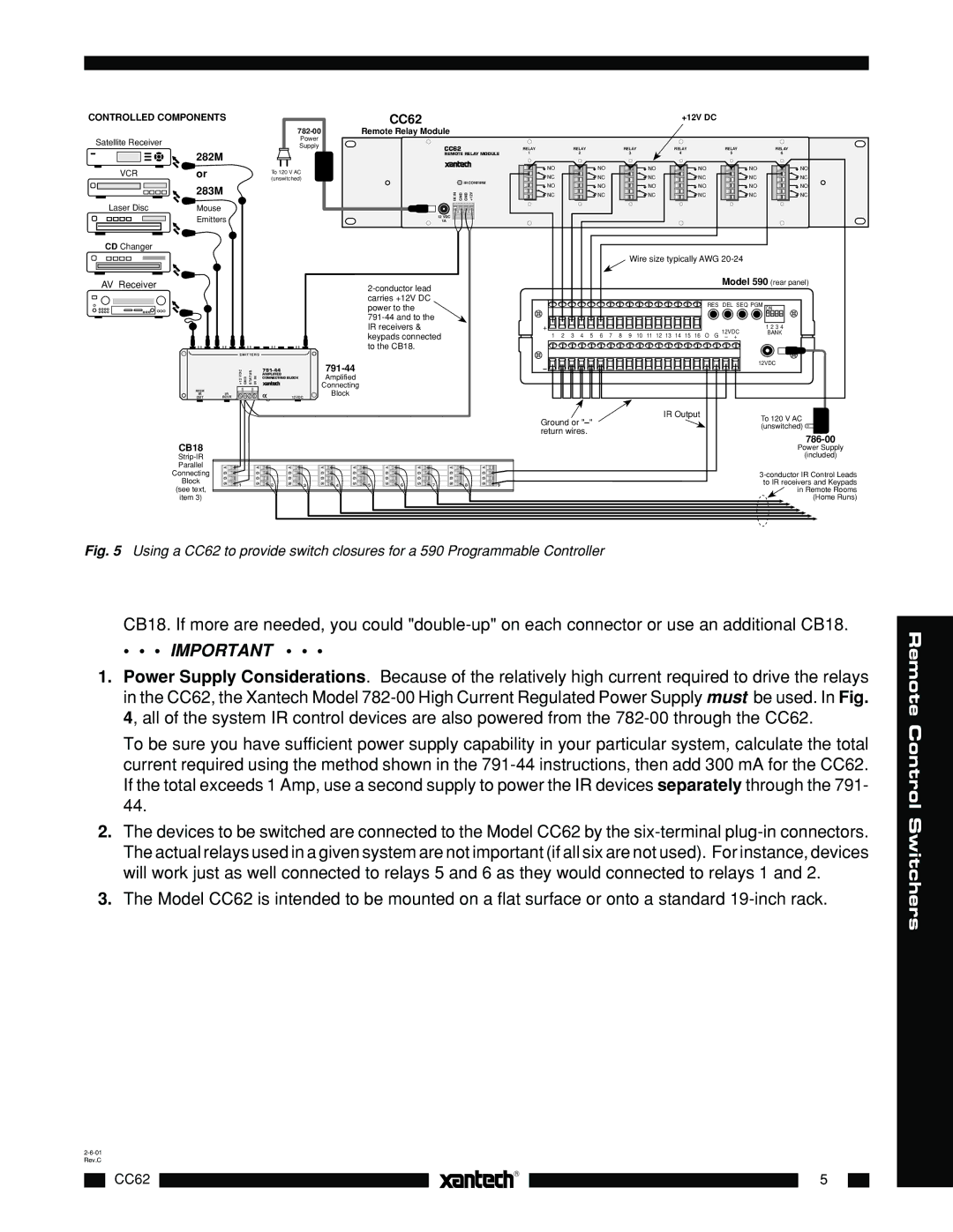
Fig. 5 Using a CC62 to provide switch closures for a 590 Programmable Controller
CB18. If more are needed, you could
• • • IMPORTANT • • •
1.Power Supply Considerations. Because of the relatively high current required to drive the relays in the CC62, the Xantech Model
To be sure you have sufficient power supply capability in your particular system, calculate the total current required using the method shown in the
2.The devices to be switched are connected to the Model CC62 by the
3.The Model CC62 is intended to be mounted on a flat surface or onto a standard
|
|
|
|
|
| |
|
|
|
CC62 |
|
| 5 |
|
|
|
|
|
|
|
|
|
|
|
Remote Control Switchers