AUDIO/VIDEO CONTROLLER/AMPLIFIER SYSTEM
MODEL MRC88 EIGHT ZONE - EIGHT SOURCE
INSTALLATION INSTRUCTIONS
NOT EXPOSE THIS APPLIANCE TO RAIN OR MOISTURE
NO USER-SERVICEABLEPARTS INSIDE
REFER SERVICING TO QUALIFIED SERVICE PERSONNEL
Page
TABLE OF CONTENTS
SECTION 1 GENERAL INFORMATION & FEATURES
SECTION 2 INSTALLATION & CONNECTIONS
SECTION 3 PRE-PROGRAMMINGTHE MRC88
SECTION 4 PROGRAMMING THE CONTROLLER
LEARNING IR COMMANDS CREATING PALETTE FILES
CONFIGURING SOURCE ICONS ON MRC88 KEYPAD LCD
PLACING COMMANDS ONTO THE VIRTUAL KEYPAD
SECTION 5 ADVANCED/EXPANDED PROGRAMMING
SECTION 7 TWEAKING THE SYSTEM
SECTION
SECTION
Page
Model MRC88
2003 Xantech Corporation
Section 1 General Information & Features
GENERAL INFORMATION
IMPORTANT NOTE A MRC88 System can be a single controller with keypads for up to Eight zones or two connected controllers and keypads for up to Sixteen zones. There are three different setup modes in the Dragon Drop-IRSoftware. The Basic mode allows quick setup and programming for an Eight zone system. It assumes all zones will use factory defaults and will behave exactly the same. The Advanced mode allows customization of system configuration for functions such as zone link, monitor lockout, unique IR programming by zone, etc. The Expanded mode allows programming of systems with more than Eight zones using linked MRC88 Controllers
Figure 1 - System Block Diagram
SYSTEM OVERVIEW
CONTROLLER/AMPLIFIER FEATURES
KEYPAD FEATURES
MRC88 FRONT PANEL FEATURES AND CONNECTIONS
System Status Power-UpMode
1.Front Panel
PROTECT ON OFF
Zone Status Active-OperationalMode
MRC88 REAR PANEL FEATURES AND CONNECTIONS
22.Source Component Input Connections
23.Source Loop-ThruConnections
MRC88 KEYPAD FEATURE DESCRIPTIONS
MRC88 KEYPAD - FRONT FEATURES 1.MRC88 Keypad
dFast Red Blink = IR Sensor INPUT or Keypad OUTPUT
MRC88 KEYPAD - REAR FEATURES AND CONNECTIONS
Section 2 Installation & Connections
INSTALLATION
Keep perforations on top cover free
MRC88
of obstructions
EXPANDED
Figure 7 - MRC88 Keypad mounting template
Note Do not tighten screws
MRC88 KEYPAD REMOVAL
CONNECTING THE MRC88 CONTROLLER/AMPLIFIER
SOURCE RELATED CONNECTIONS
Audio Connections BASIC/ADVANCED
Video Connections BASIC/ADVANCED
CSM1 Threshold Adjustments
ADVANCED
BASIC/ADVANCED
EXPANDED
BASIC/ADVANCED/EXPANDED
ZONE RELATED WIRING CONNECTIONS
EXPANDED
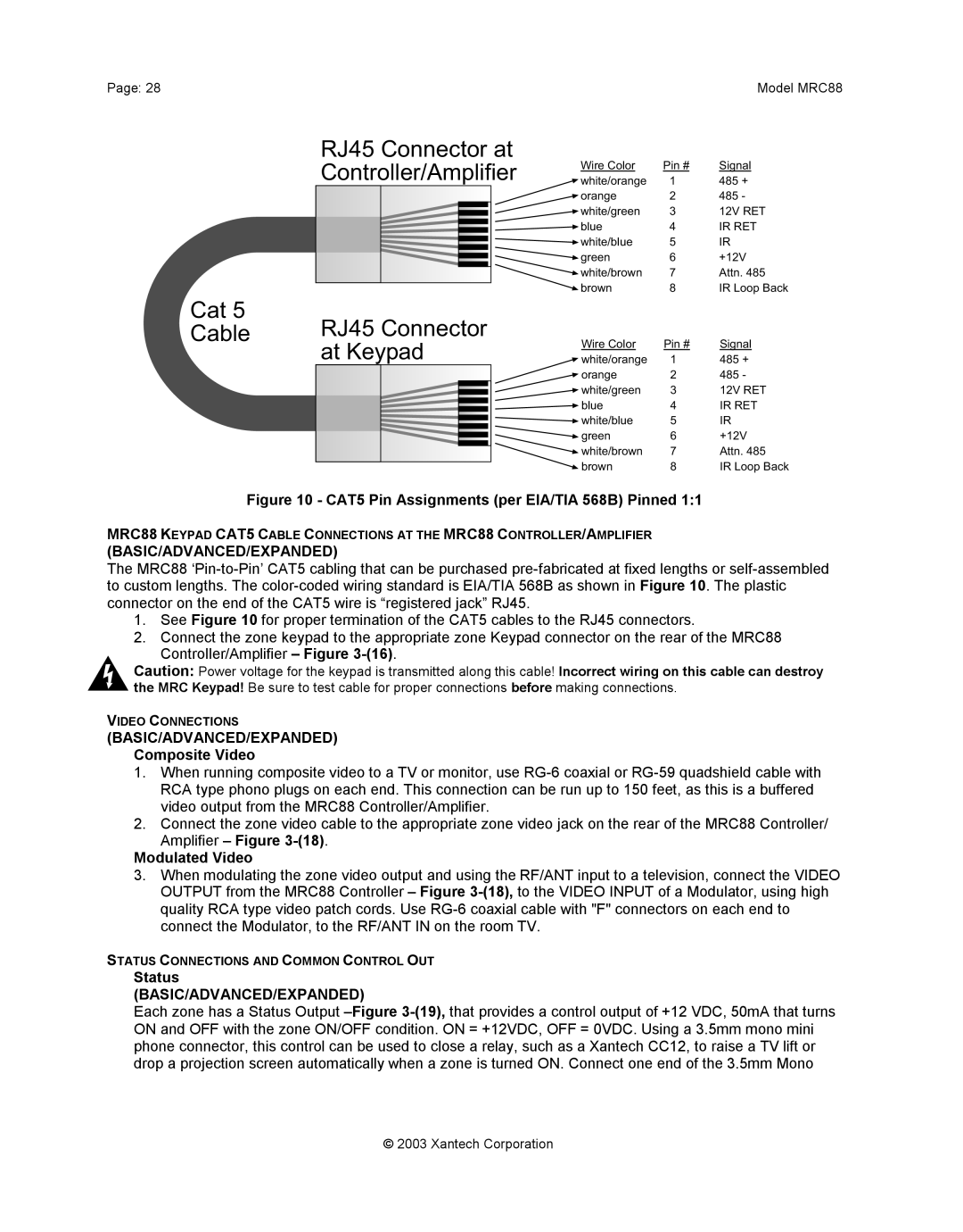
RJ45 Connector at
Controller/Amplifier
Cat 5 Cable
BASIC/ADVANCED/EXPANDED Composite Video
Control Out BASIC/ADVANCED
CO1 AND CO2 ZONES 7 & BASIC/ADVANCED/EXPANDED
ZONE IR BASIC/ADVANCED/EXPANDED
EXPANDED
Multiple Keypad Connections
Single Keypad CAT5 Connections
KEYPAD CONNECTIONS AND JUMPER SETTINGS
Table 1 - MRC88 Keypad Address Settings
Sensor Enable
Application
Zone Termination
CONNECTING SOURCE COMPONENTS
LINKING TWO MRC88 CONTROLLER/AMPLIFIER UNITS
MRC88 Connecting Block located on rear of Keypad
Figure 11 - MRC88 Keypad CAT5 Cable Lengths
1.Zones with IR Receiver ONLY
BASIC/ADVANCED/EXPANDED
BASIC/ADVANCED/EXPANDED Composite Video
Modulated Video
SETTING-UPTHE MRC88 SYSTEM
Figure 13 -TypicalMRC88 System
BASIC/ADVANCED
EXPANDED
Section 3 Pre-Programmingthe MRC88
PLANNING THE SYSTEM
BASIC MODE
ADVANCED MODE
EXPANDED MODE
SOFTWARE INSTALLATION Windows 98/ME/NT/2000/XP
INCLUDED HARDWARE & SOFTWARE ITEMS
STARTING MRC88 DRAGON DROP-IRSOFTWARE
SERIAL PORT SELECTION
STARTING A PROJECT
BUILT-INIR CODE LIBRARY BASIC/ADVANCED/EXPANDED
LEARNING IR COMMANDS Creating Palette Files
BASIC/ADVANCED/EXPANDED
LEARNING IR COMMANDS BASIC/ADVANCED/EXPANDED
Figure Built-InMfg’s IR Command Library
USING THE PALETTE EDITOR
Source BRAND selection in Palette Editor
Source COMPONENT selection in Palette Editor
To Add a New Function
To Rename an Existing Function
CREATING A PALETTE FILE BASIC/ADVANCED/EXPANDED
GETTING SOURCE COMMANDS FROM THE INTERNET
Figure 19 Creating a Palette File
EDITING BRAND, COMPONENT, AND FUNCTION LISTS
Importing CCF Files
Importing Discrete IR Hex Codes
ENTERING RS232 COMMAND STRINGS
Figure 20 Importing Discrete IR Codes
ADVANCED/EXPANDED
USING THE RS232 PALETTE EDITOR
Using PC TEST
Using MRC88 TEST
RS232 Palette Editor Window
Entering RS232 Command Strings
CREATING AN RS232 PALETTE FILE ADVANCED/EXPANDED
Figure 23 Creating an RS232 Palette File
Section 4 Programming The Controller
CONFIGURING SOURCE ICONS ON MRC88 KEYPAD LCD
BASIC/ADVANCED/EXPANDED
Figure 24 - MRC88 Keypad LCD Icon Generator
CREATING NEW ICONS
SELECTING ICONS FROM THE ICON GENERATOR
DOWNLOADING SOURCE ICONS TO THE KEYPAD
PLACING COMMANDS ONTO THE VIRTUAL KEYPAD
PLACING COMMANDS ON THE VIRTUAL KEYPAD
SELECTING IR PALETTES BASIC/ADVANCED/EXPANDED
BASIC
5.Repeat for all buttons / all sources
ADVANCED/EXPANDED
EDITING BUTTONS ON THE VIRTUAL KEYPAD
Figure Button Edit Pop-UpMenu
PUSH & HOLD TIERED COMMANDS
EDITING COMMANDS IN THE MACRO COMMAND LIST WINDOW
BASIC/ADVANCED/EXPANDED
BASIC/ADVANCED/EXPANDED
BASIC/ADVANCED/EXPANDED
Figure 27 Editing Commands
Zone 1 thru
ADVANCED/EXPANDED
PROGRAMMING POWER MANAGEMENT
BASIC/ADVANCED/EXPANDED
8.Repeat for all components necessary
BASIC
ADVANCED/EXPANDED
PROGRAMMING SENSE TRIGGER CODES ADVANCED/EXPANDED
8.Repeat for all trigger inputs desired
ZONE OPTIONS CONFIGURATION
Default settings set in BASIC Mode are as follows
NAME OF ZONE ADVANCED/EXPANDED
RC68 CODE GROUP
PRE AMP VOLUME ADJUST SETTINGS ADVANCED/EXPANDED
IR LOOP BACK SETTINGS ADVANCED/EXPANDED
BASIC
ADVANCED/EXPANDED
Figure 32 Configuring Commands for IR IN ZONE
TRANSFERRING THE PROJECT
BASIC
CONTROLLER OPTIONS PROGRAMMING
Section 5 Advanced/Expanded Programming
ZONE AUDIO INPUT
IR ROUTING
BACK-LIGHTCONTROL
MODE OF OPERATION
EXPANDED OPTIONS
RS232 SETTINGS
MONITOR LOCKOUT MODE Factory default “DISABLED”
Factory default “DISABLED”
ZONE LINKING PROGRAMMING
Figure 37 - Dynamic Zone Link Programming
Zones 1,2,3 & 4 programmed for Dynamic Linking
RS232 INPUT TRANSLATOR
LINK ALL DYNAMIC
LINK ALL STATIC
CLEAR ALL
PROGRAMMING IR COMMANDS AND SEQUENCES
Figure 39 - RC68 IR Command Macro Window
RC68+ IR CODE TRIGGERED SEQUENCER
PROGRAMMING INTERNAL AMPLIFIER COMMANDS
Figure 41 - Using Internal Amplifier Commands
Table 2 - Internal Amplifier Commands
PROGRAMMING IN EXPANDED MODE
ENABLING EXPANDED MODE
PHYSICAL CONNECTIONS IN EXPANDED MODE
RS232 CONTROL WHILE IN EXPANDED MODE
Figure 42 Expanded Controller Connections
Sources 1 through
Primary MRC88 Controller/Amplifier
From A/V loopthroughs on Primary Controller
Section 6 Completing the Programming Process
TRANSFERRING A PROJECT TO THE MRC88
UPLOADING MRC88 PROJECTS
BASIC/ADVANCED
SAVING AND BACKING-UPFILES
USING BACKUP FILES
AUTOMATIC SAVE
SAVE PROJECT AS
FIRMWARE UPGRADE OPTIONIS
WARM FIRMWARE UPGRADE
COLD FIRMWARE UPGRADE
DOWNLOADING FIRMWARE FILES FROM THE WEB
Section 7 Tweaking the System
ADVANCED/EXPANDED
MAKING FINE ADJUSTMENTS
TRIMMING SOURCE AUDIO INPUT LEVELS
ZONE ADJUSTMENTS
KEYPAD ADJUSTMENTS
POWERING THE ZONE ON AND OFF
SETTING THE VOLUME
ACCESSING TIER 2 COMMANDS
Section 8 Operating Instructions
ZONE SETTINGS
AUDIO ADJUSTMENTS BASIC/ADVANCED/EXPANDED
SYSTEM STATUS BASIC/ADVANCED
DYNAMIC ZONE LINK ADVANCED
2.Press the button for the zone to be unlinked. Z1, Z2, etc The keypad status LED’s will show ‘busy’ rapid amber flash for 10 seconds after the last button press, then ‘time out’ and return to normal use mode LED /green, LCD/normal display. The small ‘L’ will no longer appear. The zones will resume independent control
EXPANDED
TYPES OF COMMANDS
Table 2 Rear Com Port Connector Pin Out
Section 9 Appendix
RS232 CONTROL
?5SS+
7PR1+
?5SS3+
COMMANDS
COMMAND
NAME
EXAMPLES/COMMENTS
QUERIES
NAME
QUERY
RESPONSE
VOLUME LEVEL 39 Steps
KEYPAD BUTTON ID
BASS/TREBLE LEVEL
MRC88 SETTING
LEVEL in dB
MRC88 Setting
BALANCE LEVEL
Left Speaker
Right Speaker
PROBLEM
TROUBLESHOOTING
PROBABLE CAUSE AND SOLUTION
PROBABLE CAUSE AND SOLUTION
PROBLEM
a Because of the wide variety of IR coding and
PROBABLE CAUSE AND SOLUTION
PROBLEM
The following items may have interfered with the
PROBLEM
RS232 AND EXPANSION PIN OUT INFORMATION
PROBABLE CAUSE AND SOLUTION
Model MRC88
SPECIFICATIONS
CERTIFICATIONS
Video
IR Sensor
Model MRC88
Page
2003 Xantech Corporation
2003 Xantech Corporation
Model MRC88
Page
XANTECH CORPORATION
12950 Bradley Avenue, Sylmar CA
Page
Model MRC88