Manuals
/
Xantech
/
Home Audio
/
Stereo Amplifier
Xantech
PA435X
installation instructions
Bridged Mode Connections
Models:
PA435X
1
11
20
20
Download
20 pages
19.99 Kb
8
9
10
11
12
13
14
15
Troubleshooting
Specifications
Install
CONNECTING THE PA435X
Page 11
Image 11
Page 10
Page 12
Page 11
Image 11
Page 10
Page 12
Contents
MODEL PA435X FOUR CHANNEL POWER AMPLIFIER
INSTALLATION INSTRUCTIONS
Model PA435X
NO USER-SERVICEABLEPARTS INSIDE
REFER SERVICING TO QUALIFIED SERVICE PERSONNEL
Page
Figure 1 The Model PA435X Amplifier
GENERAL INFORMATION
2003 Xantech Corporation
Page
Model PA435X
PA435X PANEL AND FEATURE DESCRIPTIONS
Page
Model PA435X
PA435X
INSTALLATION - PHYSICAL LOCATION AND MOUNTING
Stereo Mode Connections
CONNECTING THE PA435X
Figure 6 - PA435X Stereo Mode Connections
Mono Mode Connections
Speaker Phasing
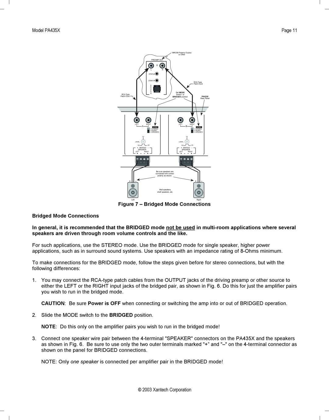
Bridged Mode Connections
Figure 7 - Bridged Mode Connections
Mute Control
Connecting the REMOTE MASTER ON/OFF MUTE CONTROL
On/Off Standby Control
Model PA435X
2003 Xantech Corporation
Page
Model PA435X
PROBABLE CAUSE AND SOLUTION
TROUBLE SHOOTING
PROBLEM
SPECIFICATIONS
2003 Xantech Corporation
Model PA435X
Page
2003 Xantech Corporation
Page
Model PA435X
2003 Xantech Corporation
Model PA435X
Page
12950 Bradley Avenue, Sylmar CA
XANTECH CORPORATION
Top
Page
Image
Contents