PA640 PANEL DESCRIPTIONS
CH6 | CH5 |
+ – | – + |
PROTECTION
+ B R I D G E D –
S P E A K E R S
CH4 | CH3 |
+ – | – + |
PROTECTION
+ B R I D G E D –
S P E A K E R S
CH2 | CH1 |
+ – | – + |
PROTECTION
+ B R I D G E D –
S P E A K E R S
P OW E R
|
|
|
|
|
| M A N U A L O N | ||
|
|
|
|
|
| M A N U A L O F F | ||
|
|
|
|
|
| ( R E M O T E O N / O F F ) | ||
|
|
|
|
|
| |||
| 1 2 0 VAC |
|
|
|
| F U S E | ||
SPEAKER IMPEDANCE | 6 0 H Z |
|
|
|
| 5 A | ||
|
|
|
|
|
|
|
| |
STEREO MODE: 8 Ohms Min. |
|
|
|
|
|
|
|
|
BRIDGED MODE: 16 Ohms Min. |
|
|
|
|
|
|
|
|
|
|
|
|
|
|
|
|
|
|
|
|
|
|
|
|
|
|
|
|
|
|
|
|
|
|
|
6 | 7 | 6 | 7 | 6 | 7 | 8 | 9 | 10 |
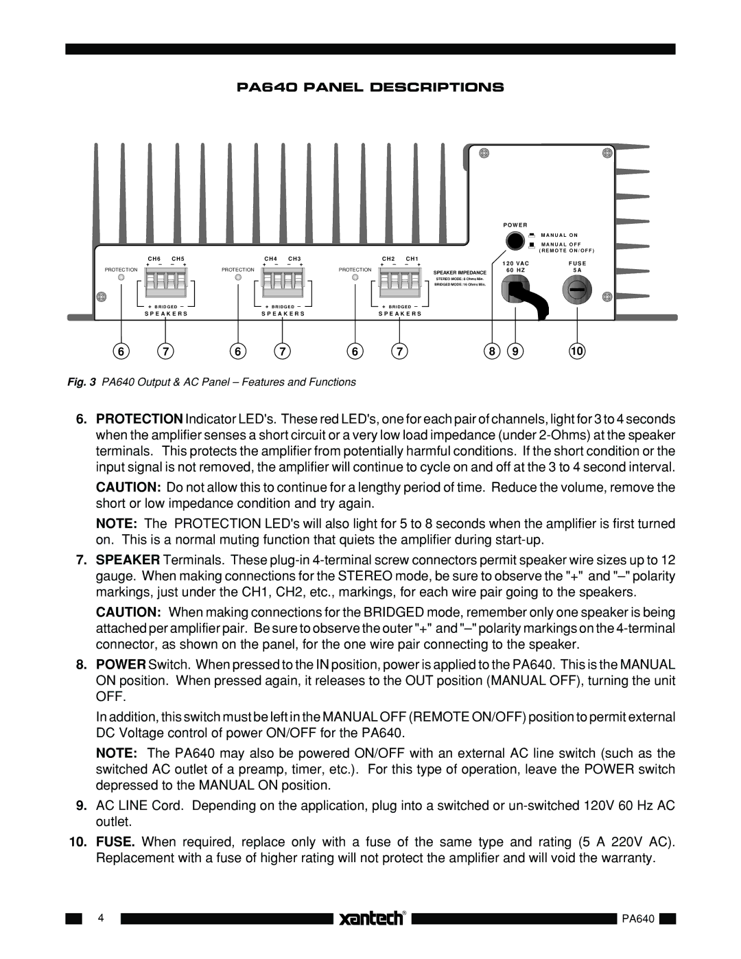
Fig. 3 PA640 Output & AC Panel – Features and Functions
6.PROTECTION Indicator LED's. These red LED's, one for each pair of channels, light for 3 to 4 seconds when the amplifier senses a short circuit or a very low load impedance (under
CAUTION: Do not allow this to continue for a lengthy period of time. Reduce the volume, remove the short or low impedance condition and try again.
NOTE: The PROTECTION LED's will also light for 5 to 8 seconds when the amplifier is first turned on. This is a normal muting function that quiets the amplifier during
7.SPEAKER Terminals. These
CAUTION: When making connections for the BRIDGED mode, remember only one speaker is being attached per amplifier pair. Be sure to observe the outer "+" and
8.POWER Switch. When pressed to the IN position, power is applied to the PA640. This is the MANUAL ON position. When pressed again, it releases to the OUT position (MANUAL OFF), turning the unit OFF.
In addition, this switch must be left in the MANUAL OFF (REMOTE ON/OFF) position to permit external DC Voltage control of power ON/OFF for the PA640.
NOTE: The PA640 may also be powered ON/OFF with an external AC line switch (such as the switched AC outlet of a preamp, timer, etc.). For this type of operation, leave the POWER switch depressed to the MANUAL ON position.
9.AC LINE Cord. Depending on the application, plug into a switched or
10.FUSE. When required, replace only with a fuse of the same type and rating (5 A 220V AC). Replacement with a fuse of higher rating will not protect the amplifier and will void the warranty.
4
PA640
