INSTALLATION (cont'd)
CONNECTING THE PA640
I When making connections to the PA640 be sure the power cord is unplugged. Proceed as follows:
Stereo Mode Connections
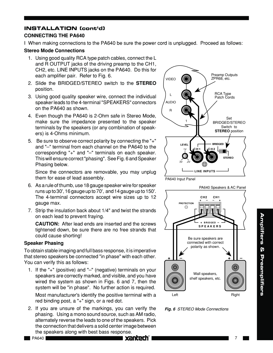
1.Using good quality RCA type patch cables, connect the L and R OUTPUT jacks of the driving preamp to the CH1, CH2, etc. LINE INPUTS jacks on the PA640. Do this for each amplifier pair. Refer to Fig. 6.
2.Slide the BRIDGED/STEREO switch to the STEREO position.
3.Using good quality speaker wire, connect the individual speaker leads to the
4.Even though the PA640 is
5.Be sure to observe correct polarity by connecting the "+" and
VIDEO
L
AUDIO
R![]()
1
LEVEL
1V | C H 1 |
3V .2V
Preamp Outputs
ZPR68, etc.
RCA Type
Patch Cords
Set
BRIDGED/STEREO
Switch to
STEREO position
BRIDGED
C H 2
STEREO
Since the connectors are removable, you may unplug them for ease of lead assembly.
6.As a rule of thumb, use 18 gauge speaker wire for speaker runs up to 30', 16 gauge up to 70', and 14 gauge up to 150'. The
7.Strip the insulation back about 1/4" and twist the strands on each lead to prevent fraying.
CAUTION: After lead ends are inserted and the screws tightened down, be sure there are no free strands that could cause shorting!
Speaker Phasing
To obtain stable imaging and full bass response, it is imperative that stereo speakers be connected "in phase" with each other. You can verify this as follows:
1.If the "+" (positive) and
![]() LINE INPUTS
LINE INPUTS ![]()
PA640 Input Panel
PA640 Speakers & AC Panel
CH2 | CH1 |
+ – | – + |
PROTECTION
+B R I D G E D –
S P E A K E R S
Be sure speakers are connected with correct polarity as shown.
+ | – | + | – |
Wall speakers,
shelf speakers, etc.
Amplifiers & Preamplifiers
| Most manufacturer's identify the positive terminal with a | Left | Right | ||||
| red binding post, a "+" sign, or a red dot. |
|
|
| |||
2. If you are unsure of the markings, you can verify the | Fig. 6 STEREO Mode Connections |
|
| ||||
| phasing. Using a mono sound source, such as AM radio, |
|
|
| |||
| alternately reverse the leads to one of the speakers. Pick |
|
|
| |||
| the connection that delivers a solid center image between |
|
|
| |||
| the speakers along with best bass response. |
|
|
| |||
|
|
| |
|
|
|
|
|
|
|
|
| 7 |
| |
| PA640 |
|
|
|
| ||
|
|
|
|
|
|
|
|
|
|
|
|
|
|
|
|