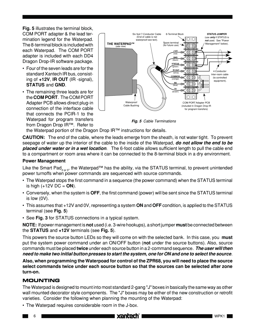
WPK8, WPK1, WPK4, WPK6 specifications
Xantech, a renowned leader in audio and video distribution technology, offers a range of wireless keypad controllers designed to enhance user experience and simplify the control of sophisticated A/V systems. Among their notable products are the WPK8, WPK4, WPK1, and WPK6, each tailored to meet various user needs while maintaining quality and efficiency.The Xantech WPK8 is an eight-button wireless keypad that allows for versatility in controlling multiple zones or devices. Its compact design and intuitive layout make it ideal for residential or commercial applications. The WPK8 features a two-way communication system, ensuring that users receive real-time feedback from their A/V components. This creates a seamless user experience, as commands are executed promptly and accurately.
Moving to the WPK4, this four-button wireless keypad is designed for environments where space is a premium. Despite its smaller size, the WPK4 maintains robust functionality, allowing users to control essential A/V functions such as volume, source selection, and power on/off. It also incorporates a simple installation process, ensuring quick setup without compromising on performance.
For users seeking a single-point solution, the WPK1 is an ideal option. This one-button wireless keypad simplifies the control experience, allowing users to command a single function, like turning on the system or changing the input. The WPK1’s simplistic design is perfect for users who prefer minimalism while still wanting effective control over their audio and video devices.
The WPK6, on the other hand, offers a middle ground with its six-button layout. Designed for intermediate applications, it allows users to control multiple functions without overwhelming complexities. Additionally, all these keypads utilize advanced wireless technology for reliable performance and reduced interference, making them suitable for various installation scenarios.
Each keypad is designed with user convenience in mind, featuring customizable options for button programming. They also boast a long battery life, ensuring longevity and minimizing frequent maintenance. Designed to integrate seamlessly with Xantech’s extensive range of A/V distribution products, these keypads reflect Xantech’s commitment to pioneering technology and user-friendly interfaces. With their distinctive features and reliability, the WPK series allows users to enjoy enhanced control over their audiovisual experiences in any setting.

