Power Management Setup |
|
|
| |||
|
|
|
| |||
|
| CMOS Setup |
| |||
|
|
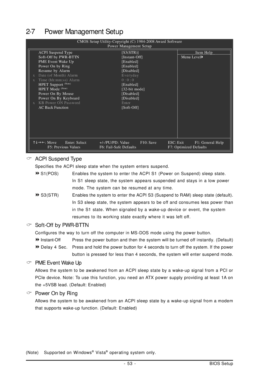
| Power Management Setup |
|
| |
| ACPI Suspend Type | [S3(STR)] |
|
| Item Help | |
| Menu Level | |||||
| PME Event Wake Up | [Enabled] |
|
|
| |
| Power On by Ring | [Enabled] |
|
|
| |
| Resume by Alarm | [Disabled] |
|
|
| |
x Date (of Month) Alarm | Everyday |
|
|
| ||
x | Time (hh:mm:ss) Alarm | 0 : 0 : 0 |
|
|
| |
| HPET Support (Note) | [Enabled] |
|
|
| |
| HPET Mode (Note) |
|
| |||
| Power On By Mouse | [Disabled] |
|
|
| |
| Power On By Keyboard | [Disabled] |
|
|
| |
x KB Power ON Password | Enter |
|
|
| ||
| AC Back Function |
|
|
| ||
: Move | Enter: Select | F10: Save | ESC: Exit | F1: General Help | ||
| F5: Previous Values | F6: |
| F7: Optimized Defaults | ||
|
|
|
|
|
| |
| ACPI Suspend Type |
|
|
|
| |
| Specifies the ACPI sleep state when the system enters suspend. |
| ||||
| S1(POS) | Enables the system to enter the ACPI S1 (Power on Suspend) sleep state. | ||||
|
| In S1 sleep state, the system appears suspended and stays in a low power | ||||
|
| mode. The system can be resumed at any time. |
| |||
| S3(STR) | Enables the system to enter the ACPI S3 (Suspend to RAM) sleep state (default). | ||||
|
| In S3 sleep state, the system appears to be off and consumes less power than | ||||
|
| in the S1 state. When signaled by a | ||||
|
| resumes to its working state exactly where it was left off. |
| |||
Soft-Off by PWR-BTTN
Configures the way to turn off the computer in
![]()
![]() Delay 4 Sec. Press and hold the power button for 4 seconds to turn off the system. If the power button is pressed for less than 4 seconds, the system will enter suspend mode.
Delay 4 Sec. Press and hold the power button for 4 seconds to turn off the system. If the power button is pressed for less than 4 seconds, the system will enter suspend mode.
PME Event Wake Up
Allows the system to be awakened from an ACPI sleep state by a
Power On by Ring
Allows the system to be awakened from an ACPI sleep state by a
(Note) Supported on Windows® Vista® operating system only.
- 53 - | BIOS Setup |