4-6 Time Repair
Based on the Microsoft Volume Shadow Copy Services technology, Time Repair allows you to quickly back up and restore your system data in the Windows Vista operating system. Time Repair supports NTFS file system and can restore system data on PATA and SATA hard drives.
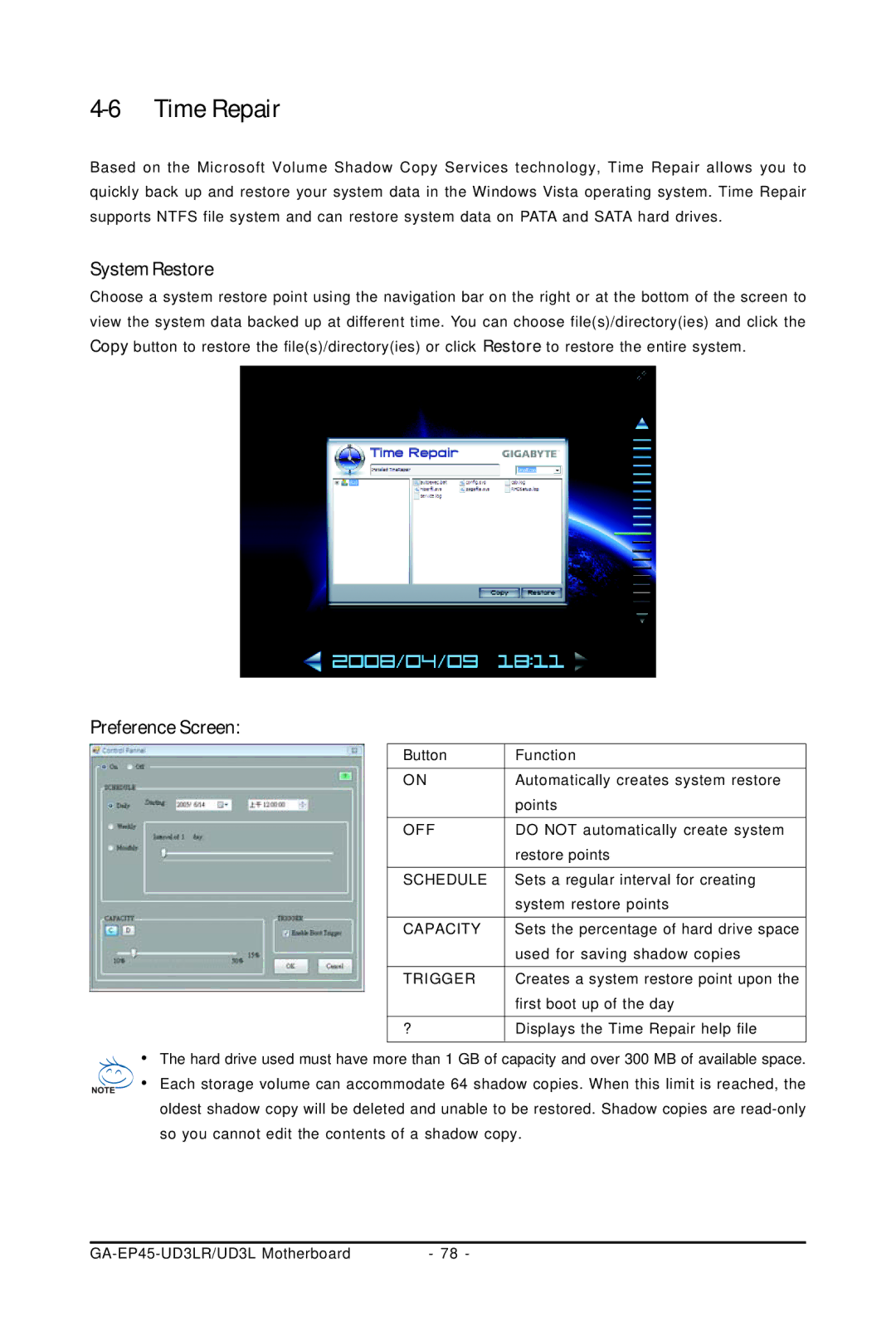
System Restore
Choose a system restore point using the navigation bar on the right or at the bottom of the screen to view the system data backed up at different time. You can choose file(s)/directory(ies) and click the Copy button to restore the file(s)/directory(ies) or click Restore to restore the entire system.
Preference Screen:
Button | Function |
ON | Automatically creates system restore |
| points |
OFF | DO NOT automatically create system |
| restore points |
SCHEDULE | Sets a regular interval for creating |
| system restore points |
CAPACITY | Sets the percentage of hard drive space |
| used for saving shadow copies |
TRIGGER | Creates a system restore point upon the |
| first boot up of the day |
? | Displays the Time Repair help file |
•The hard drive used must have more than 1 GB of capacity and over 300 MB of available space.
•Each storage volume can accommodate 64 shadow copies. When this limit is reached, the oldest shadow copy will be deleted and unable to be restored. Shadow copies are
- 78 - |