GA-EP45-UD3LR/ GA-EP45-UD3L
Users Manual
Motherboard
GA-EP45-UD3LR GA-EP45-UD3L Oct. 8
Motherboard
GA-EP45-UD3LR/GA-EP45-UD3L
Copyright
Disclaimer
Documentation Classifications
Identifying Your Motherboard Revision
Table of Contents
GA-EP45-UD3LR/GA-EP45-UD3L Motherboard Layout
1-3-1
1-4-1
Chapter 3 Drivers Installation
Chapter 4 Unique Features
Configuring SATA Hard Drives
Chapter 5 Appendix
Box Contents
Optional Items
GA-EP45-UD3LR/GA-EP45-UD3L
GA-EP45-UD3LR/GA-EP45-UD3L Motherboard Layout
Block Diagram
4 PCI Express
LPC Bus
Chapter 1 Hardware Installation
1-1 Installation Precautions
Product Specifications
The PCI Express x16 slot conforms to PCI Express 2.0 standard
Internal Connectors
Page
1-3 Installing the CPU and CPU Cooler
1-3-1 Installing the CPU
CPU Socket Lever
1-3-2 Installing the CPU Cooler
Direction of the Arrow Sign on the Male Push Pin
Male Push Pin The Top of Female Push Pin Female Push Pin
1-4 Installing the Memory
1-4-1 Dual Channel Memory Configuration
1-4-2 Installing a Memory
1-5 Installing an Expansion Card
PCI Express x1 Slot PCI Express x16 Slot PCI Slot
1-6 Back Panel Connectors
Optical S/PDIF Out Connector
Coaxial S/PDIF Out Connector
PS/2 Keyboard and PS/2 Mouse Port
Center/Subwoofer Speaker Out Jack Orange
Rear Speaker Out Jack Black
Side Speaker Out Jack Gray
Line In Jack Blue
1-7 Internal Connectors
PHASE LED
ATX12V
CDIN
1/2 ATX12V/ATX 2x2 12V Power Connector and 2x12 Main Power Connector
+5V Only for 2x12-pinATX
6 FDD Floppy Disk Drive Connector
3/4/5 CPUFAN/SYSFAN1/SYSFAN2/PWRFAN Fan Headers
headers
7 IDE IDE Connector
8 SATA20/1/2/3/4/5 SATA 3Gb/s Connectors
SATA20
SATA24
9 PWRLED System Power LED Header
8 SATA20/1/2/3/4/5 SATA 3Gb/s Connectors
Only for GA-EP45-UD3L
10 FAUDIO Front Panel Audio Header
11 FPANEL Front Panel Header
12 CDIN CD In Connector, Black
13 SPDIFI S/PDIF In Header, Red
14 SPDIFO S/PDIF Out Header
15 FUSB1/FUSB2 USB Headers, Yellow
Do not plug the IEEE 1394 bracket 2x5-pin cable into the USB header
16 LPT Parallel Port Header
17 COMA Serial Port Header, White
18 CI Chassis Intrusion Header
19 CLRCMOS Clearing CMOS Jumper
20 BAT BATTERY
21 PHASE LED
You may clear the CMOS values by removing the battery
1. Turn off your computer and unplug the power cord
Chapter 2 BIOS Setup
A. The LOGO Screen Default
2-1 Startup Screen
B. The POST Screen
DEL BIOS SETUP\Q-FLASH
Sample BIOS Version GA-EP45-UD3L E19
BIOS Setup Program Function Keys
2-2 The Main Menu
Main Menu Help
Standard CMOS Features
Advanced BIOS Features
Power Management Setup
PnP/PCI Configurations
2-3 MB Intelligent TweakerM.I.T
Clock Chip Control
DRAM Performance Control
Mother Board Voltage Control
Robust Graphics Booster
CPU Clock Ratio Note
Fine CPU Clock Ratio Note
CPU Frequency
CPU Host Frequency Mhz
PCI Express Frequency Mhz
C.I.A.2
Advanced Clok Control
CPU Clock Drive
PCI Express Clock Drive
CPU Clock Skew
MCH Clock Skew
Command RateCMD
CAS Latency Time
tRCD
tRAS
Channel A/B Timing Settings
tRD Phase0 Adjustment
tRD Phase1 Adjustment
tRD Phase2 Adjustment
Channel A/B Driving Settings
DDR Write Training
Driving Strength Profile
Data Driving Pull-Up Level
Load-Line Calibration
CPU Vcore
CPU Termination
CPU PLL
Standard CMOS Features
Date
Time
IDE Channel 0, 1 Master/Slave
Floppy 3 Mode Support
IDE Channel 2, 3 Master, IDE Channel 4 Master/Slave
Drive A
Halt On
Advanced BIOS Features
Hard Disk Boot Priority
First/Second/Third Boot Device
Password Check
CPU Multi-Threading Note
Limit CPUID Max. to 3 Note
No-Execute Memory Protect Note
CPU Enhanced Halt C1ENote
Delay For HDD Secs
Full Screen LOGO Show
Init Display First
Integrated Peripherals
SATA RAID/AHCI Mode Intel ICH10R Southbridge
Disabled
Enables RAID for the SATA controllers
SMART LAN LAN Cable Diagnostic Function
USB Controller
USB 2.0 Controller
USB Keyboard Support
Onboard LAN Boot ROM
Parallel Port Mode
Onboard IDE Controller JMicron 368 Chip
Onboard Serial Port
Power Management Setup
Power On by Ring
Soft-Off by PWR-BTTN
PME Event Wake Up
Resume by Alarm
HPET Mode Note
Power On By Mouse
Power On By Keyboard
2-8 PnP/PCI Configurations
PCI1 IRQ Assignment
PCI2 IRQ Assignment
BIOS auto-assigns IRQ to the first PCI slot. Default
Reset Case Open Status
Current System/CPU Temperature
Current CPU/SYSTEM/POWER FAN Speed RPM
CPU Warning Temperature
CPU Smart FAN Mode
CPU Smart FAN Control
2-10 Load Fail-Safe Defaults
2-11 Load Optimized Defaults
Load Optimized DefaultsSaveY/N?& ExitN Setup
Set Supervisor/User Password
2-12
Supervisor Password
User Password
2-13 Save & Exit Setup
2-14 Exit Without Saving
Chapter 3 Drivers Installation
3-1 Installing Chipset Drivers
3-2 Application Software
3-3 Technical Manuals
3-4 Contact
3-5 System
Drivers Installation
This page provides the basic system information
3-6 Download Center
Chapter 4 Unique Features
4-1 Xpress Recovery2
Before You Begin
System Requirements
Installation and Configuration
A. Installing Windows XP and Partitioning the Hard Drive
4. After the operating system is installed, right-click the My Computer icon on your desktop and select Manage Figure 4. Go to Computer Management to check disk allocation. Xpress Recovery2 will save the backup file to the unallocated space black stripe along the topFigure 5. Please note that if there is no enough unallocated space, Xpress Recovery2 cannot save the backup file
B. Accessing Xpress Recovery2
C. Using the Backup Function in Xpress Recovery2
D. Using the Restore Function in Xpress Recovery2
E. Removing the Backup
F. Exiting Xpress Recovery2
4-2 BIOS Update Utilities
4-2-1 Updating the BIOS with the Q-Flash Utility
A. Before You Begin
What is DualBIOSTM?
B. Updating the BIOS
Copy BIOS completed - Pass
Please press any key to continue
Load Optimized DefaultsSaveY/N?& ExitY Setup
4-2-2 Updating the BIOS with the @BIOS Utility
B. Using @BIOS
C. After Updating the BIOS
1. Update the BIOS Using the Internet Update Function
4-3 EasyTune
The EasyTune 6 Interface Tabs Information
The Dynamic Energy Saver Advanced Interface A. Meter Mode
Meter Mode - Button Information Table
4-4 Dynamic Energy Saver Advanced
B. Total Mode
Total Mode - Button Information Table
C. Stealth Mode
Directions for using Q-Share
4-5 Q-Share
Options Descriptions
System Restore
4-6 Time Repair
Preference Screen
5-1 Configuring SATA Hard Drives
5-1-1 Configuring the Onboard SATA Controller
To configure SATA hard drives, follow the steps below
A. Installing SATA hard drives in your computer
B. Configuring SATA controller mode in BIOS Setup
C. Configuring a RAID array in RAID BIOS
Create RAID Volume
Step
Step
GA-EP45-UD3LR/UD3L Motherboard
WARNING ALL DATA ON SELECTED DISKS WILL BE LOST
Delete RAID Volume
DELETE VOLUME VERIFICATION ALL DATA IN THE VOLUME WILL BE LOST
Required for AHCI and RAID Mode
5-1-2 Making a SATA RAID/AHCI Driver Diskette
Page
5-1-3 Installing the SATA RAID/AHCI Driver and Operating System
A. Installing Windows XP
Page
WindowsXP Professional Setup Welcome to Setup
B. Installing Windows Vista
Step
Configuring Audio Input and Output
Configuring 2/4/5.1/7.1-Channel Audio
A. Configuring Speakers
5-2-1
B. Configuring Sound Effect
C. Activating an AC97 Front Panel Audio Module
D. Muting the Back Panel Audio For HD Audio Only
5-2-2 Installing the S/PDIF In Cable Optional
A. Installing the S/PDIF In Cable
S/PDIF In
C. Configuring S/PDIF out
S/PDIF Out
B. Conneting a S/PDIF out Cable
5-2-3 Configuring Microphone Recording
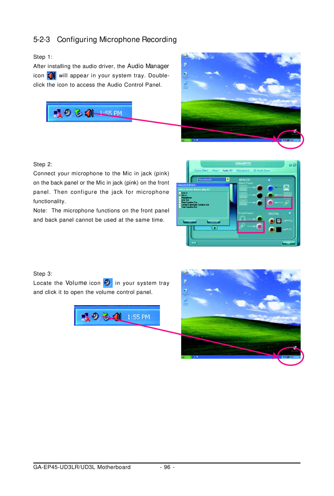
Select Realtek HD Audio Input in the Mixer device list
5-2-4 Using the Sound Recorder
Recording the Sound
Playing the Sound
5-3 Troubleshooting
5-3-1 Frequently Asked Questions
5-3-2 Troubleshooting Procedure
Correctly insert the
The power supply
device, connector
monitor might fail
CPU or CPU socket
WEEE Symbol Statement
5-4 Regulatory Statements
Regulatory Notices
Our Commitment to Preserving the Environment
China Restriction of Hazardous Substances Table
GA-EP45-UD3LR/UD3L Motherboard
Appendix
GA-EP45-UD3LR/UD3L Motherboard
Appendix
GA-EP45-UD3LR/UD3L Motherboard
Appendix
GA-EP45-UD3LR/UD3L Motherboard
Contact Us
GIGABYTE Global Service System