OPERATION
■Mode comparison and operation outline
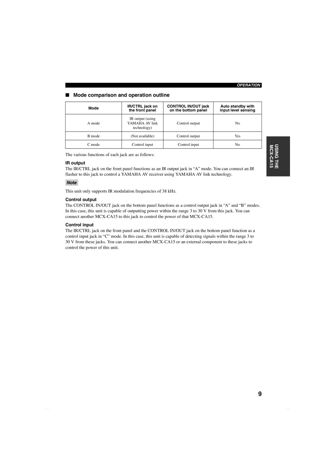
Mode | IR/CTRL jack on | CONTROL IN/OUT jack | Auto standby with | |
the front panel | on the bottom panel | input level sensing | ||
| ||||
|
|
|
| |
| IR output (using |
|
| |
A mode | YAMAHA AV link | Control output | No | |
| technology) |
|
| |
|
|
|
| |
B mode | (Not available) | Control output | Yes | |
|
|
|
| |
C mode | Control input | Control input | No | |
|
|
|
|
The various functions of each jack are as follows:
IR output
The IR/CTRL jack on the front panel functions as an IR output jack in “A” mode. You can connect an IR flasher to this jack to control a YAMAHA AV receiver using YAMAHA AV link technology.
Note
This unit only supports IR modulation frequencies of 38 kHz.
Control output
The CONTROL IN/OUT jack on the bottom panel functions as a control output jack in “A” and “B” modes. In this case, this unit is capable of outputting power within the range 3 to 30 V from this jack. You can connect another
Control input
The IR/CTRL jack on the front panel and the CONTROL IN/OUT jack on the bottom panel function as a control input jack in “C” mode. In this case, this unit is capable of detecting signals within the range 3 to 30 V from these jacks. You can connect another
USING THE
9