1.Engage the drive clutch control handle (squeeze handle against the upper handle). Measure the spring on the drive clutch cable. It should measure approximately
2.If adjustment is necessary, loosen the screw
which secures the cable bracket to the upper handle.
Lower | Notch | 3. Slide the cable bracket up or down as |
| ||
Handle |
| necessary. |
4.Check the spring length as instructed in step one.
Figure 10
4.Turn the lower handle around so the notches on the bottom of the lower handle are facing forward as shown in Figure 10.
5.Reassemble, placing the bottom holes in the handle over the weld pins in the handle mounting bracket.
6.Reassemble the upper handle.
7.Place the hairpin clips in the inner holes in the weld pins and attach the starter rope as instructed in the
DRIVE CLUTCH CONTROL
ADJUSTMENT
Adjust the drive clutch control if
1.the mower
2.the mower does not
3.drive belt is slipping (unit hesitates while engine maintains the same speed).
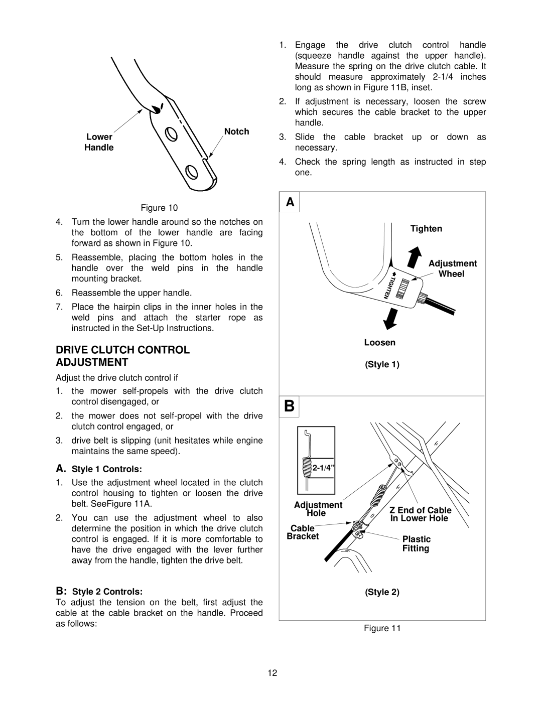
A.Style 1 Controls:
1.Use the adjustment wheel located in the clutch control housing to tighten or loosen the drive belt. SeeFigure 11A.
2.You can use the adjustment wheel to also determine the position in which the drive clutch control is engaged. If it is more comfortable to have the drive engaged with the lever further away from the handle, tighten the drive belt.
B:Style 2 Controls:
To adjust the tension on the belt, first adjust the cable at the cable bracket on the handle. Proceed as follows:
A |
| |
| Tighten | |
| Adjustment | |
| Wheel | |
| Loosen | |
| (Style 1) | |
B |
| |
| ||
Adjustment | Z End of Cable | |
Hole | ||
In Lower Hole | ||
Cable | ||
| ||
Bracket | Plastic | |
| Fitting | |
| (Style 2) |
Figure 11
12