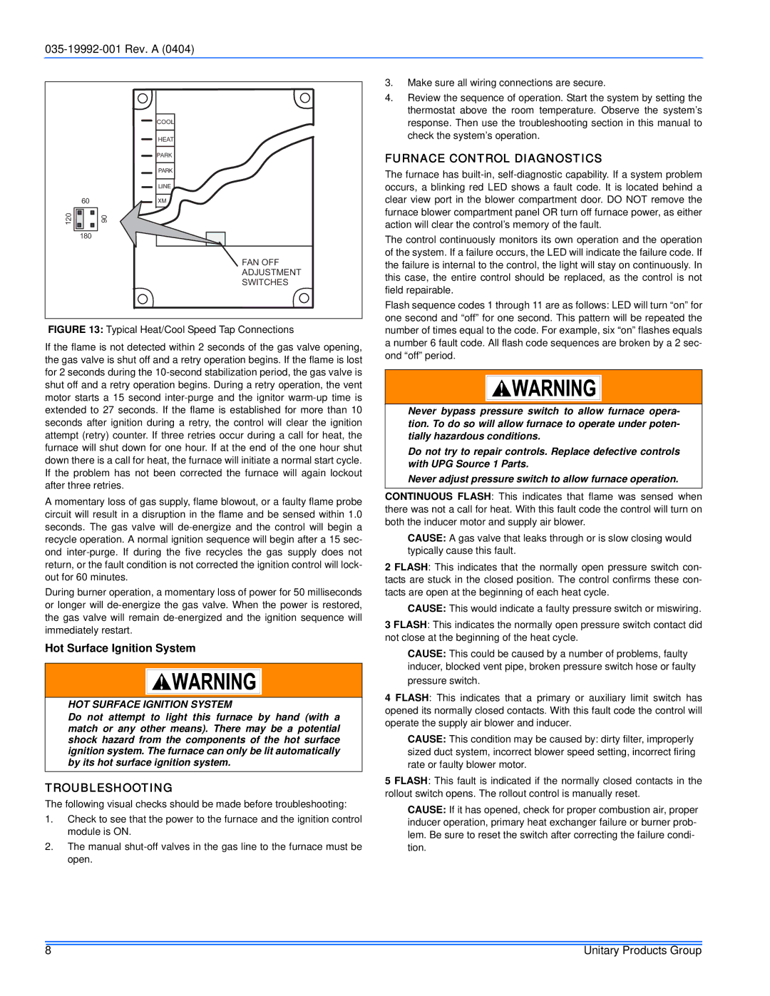
COOL
HEAT
PARK
PARK
LINE
60XM
120
180
FAN OFF
ADJUSTMENT
SWITCHES
FIGURE 13: Typical Heat/Cool Speed Tap Connections
If the flame is not detected within 2 seconds of the gas valve opening, the gas valve is shut off and a retry operation begins. If the flame is lost for 2 seconds during the 10-second stabilization period, the gas valve is shut off and a retry operation begins. During a retry operation, the vent motor starts a 15 second inter-purge and the ignitor warm-up time is extended to 27 seconds. If the flame is established for more than 10 seconds after ignition during a retry, the control will clear the ignition attempt (retry) counter. If three retries occur during a call for heat, the furnace will shut down for one hour. If at the end of the one hour shut down there is a call for heat, the furnace will initiate a normal start cycle. If the problem has not been corrected the furnace will again lockout after three retries.
A momentary loss of gas supply, flame blowout, or a faulty flame probe circuit will result in a disruption in the flame and be sensed within 1.0 seconds. The gas valve will de-energize and the control will begin a recycle operation. A normal ignition sequence will begin after a 15 sec- ond inter-purge. If during the five recycles the gas supply does not return, or the fault condition is not corrected the ignition control will lock- out for 60 minutes.
During burner operation, a momentary loss of power for 50 milliseconds or longer will de-energize the gas valve. When the power is restored, the gas valve will remain de-energized and the ignition sequence will immediately restart.
Hot Surface Ignition System
HOT SURFACE IGNITION SYSTEM
Do not attempt to light this furnace by hand (with a match or any other means). There may be a potential shock hazard from the components of the hot surface ignition system. The furnace can only be lit automatically by its hot surface ignition system.
TROUBLESHOOTING
The following visual checks should be made before troubleshooting:
1.Check to see that the power to the furnace and the ignition control module is ON.
2.The manual
open.
3.Make sure all wiring connections are secure.
4.Review the sequence of operation. Start the system by setting the thermostat above the room temperature. Observe the system’s response. Then use the troubleshooting section in this manual to check the system’s operation.
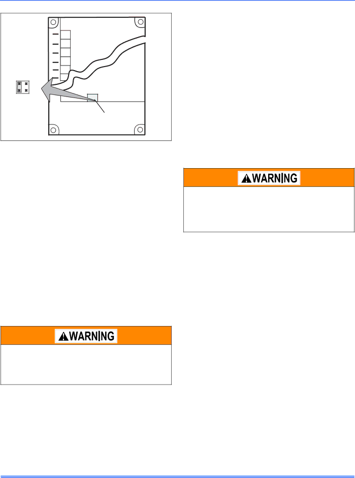
FURNACE CONTROL DIAGNOSTICS
The furnace has
The control continuously monitors its own operation and the operation of the system. If a failure occurs, the LED will indicate the failure code. If the failure is internal to the control, the light will stay on continuously. In this case, the entire control should be replaced, as the control is not field repairable.
Flash sequence codes 1 through 11 are as follows: LED will turn “on” for one second and “off” for one second. This pattern will be repeated the number of times equal to the code. For example, six “on” flashes equals a number 6 fault code. All flash code sequences are broken by a 2 sec- ond “off” period.
Never bypass pressure switch to allow furnace opera- tion. To do so will allow furnace to operate under poten- tially hazardous conditions.
Do not try to repair controls. Replace defective controls with UPG Source 1 Parts.
Never adjust pressure switch to allow furnace operation.
CONTINUOUS FLASH: This indicates that flame was sensed when there was not a call for heat. With this fault code the control will turn on both the inducer motor and supply air blower.
CAUSE: A gas valve that leaks through or is slow closing would typically cause this fault.
2 FLASH: This indicates that the normally open pressure switch con- tacts are stuck in the closed position. The control confirms these con- tacts are open at the beginning of each heat cycle.
CAUSE: This would indicate a faulty pressure switch or miswiring.
3 FLASH: This indicates the normally open pressure switch contact did not close at the beginning of the heat cycle.
CAUSE: This could be caused by a number of problems, faulty inducer, blocked vent pipe, broken pressure switch hose or faulty pressure switch.
4 FLASH: This indicates that a primary or auxiliary limit switch has opened its normally closed contacts. With this fault code the control will operate the supply air blower and inducer.
CAUSE: This condition may be caused by: dirty filter, improperly sized duct system, incorrect blower speed setting, incorrect firing rate or faulty blower motor.
5 FLASH: This fault is indicated if the normally closed contacts in the rollout switch opens. The rollout control is manually reset.
CAUSE: If it has opened, check for proper combustion air, proper inducer operation, primary heat exchanger failure or burner prob- lem. Be sure to reset the switch after correcting the failure condi- tion.
8 | Unitary Products Group |