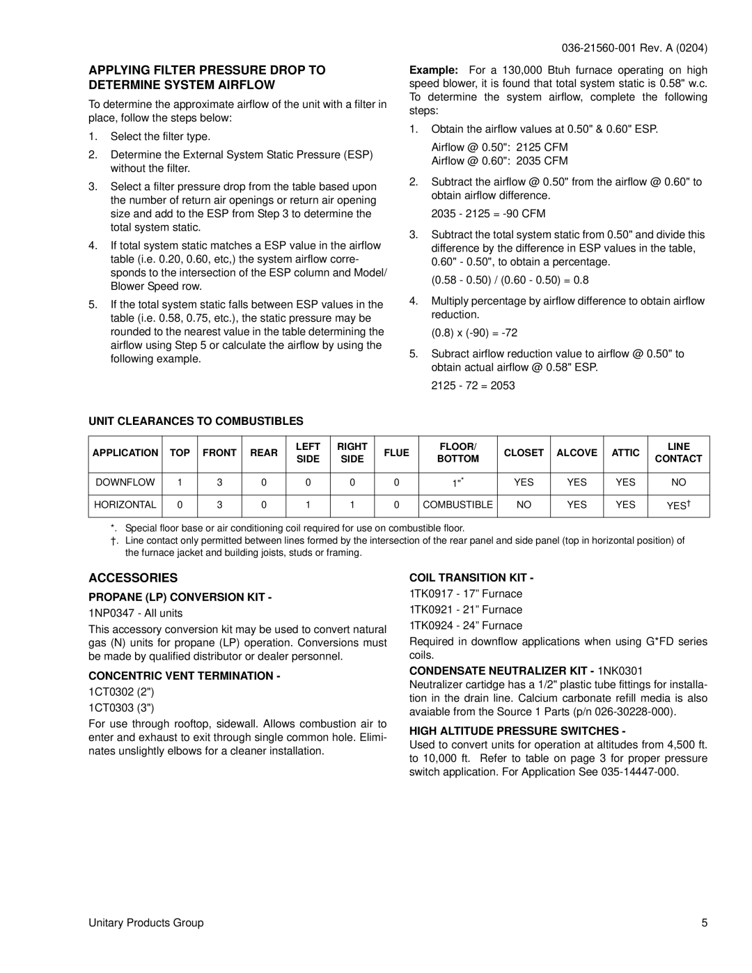
APPLYING FILTER PRESSURE DROP TO DETERMINE SYSTEM AIRFLOW

To determine the approximate airflow of the unit with a filter in place, follow the steps below:

1.Select the filter type.

2.Determine the External System Static Pressure (ESP) without the filter.

3.Select a filter pressure drop from the table based upon the number of return air openings or return air opening size and add to the ESP from Step 3 to determine the total system static.

4.If total system static matches a ESP value in the airflow table (i.e. 0.20, 0.60, etc,) the system airflow corre- sponds to the intersection of the ESP column and Model/ Blower Speed row.

5.If the total system static falls between ESP values in the table (i.e. 0.58, 0.75, etc.), the static pressure may be rounded to the nearest value in the table determining the airflow using Step 5 or calculate the airflow by using the following example.

UNIT CLEARANCES TO COMBUSTIBLES

036-21560-001 Rev. A (0204)

Example: For a 130,000 Btuh furnace operating on high speed blower, it is found that total system static is 0.58" w.c. To determine the system airflow, complete the following steps:

1.Obtain the airflow values at 0.50" & 0.60" ESP.

Airflow @ 0.50": 2125 CFM

Airflow @ 0.60": 2035 CFM

2.Subtract the airflow @ 0.50" from the airflow @ 0.60" to obtain airflow difference.

2035 - 2125 = -90 CFM

3.Subtract the total system static from 0.50" and divide this difference by the difference in ESP values in the table, 0.60" - 0.50", to obtain a percentage.

(0.58 - 0.50) / (0.60 - 0.50) = 0.8

4.Multiply percentage by airflow difference to obtain airflow reduction.

(0.8) x (-90) = -72

5.Subract airflow reduction value to airflow @ 0.50" to obtain actual airflow @ 0.58" ESP.

2125 - 72 = 2053

APPLICATION

TOP

FRONT

REAR

LEFT

RIGHT

FLUE

FLOOR/

CLOSET

ALCOVE

ATTIC

LINE

SIDE

SIDE

BOTTOM

CONTACT


DOWNFLOW

1

3

0

0

0

0

1"*

YES

YES

YES

NO

HORIZONTAL

0

3

0

1

1

0

COMBUSTIBLE

NO

YES

YES

YES

*. Special floor base or air conditioning coil required for use on combustible floor.

†.Line contact only permitted between lines formed by the intersection of the rear panel and side panel (top in horizontal position) of the furnace jacket and building joists, studs or framing.

ACCESSORIES

PROPANE (LP) CONVERSION KIT -

1NP0347 - All units

This accessory conversion kit may be used to convert natural gas (N) units for propane (LP) operation. Conversions must be made by qualified distributor or dealer personnel.

CONCENTRIC VENT TERMINATION -

1CT0302 (2") 1CT0303 (3")

For use through rooftop, sidewall. Allows combustion air to enter and exhaust to exit through single common hole. Elimi- nates unslightly elbows for a cleaner installation.

COIL TRANSITION KIT -

1TK0917 - 17” Furnace

1TK0921 - 21” Furnace

1TK0924 - 24” Furnace

Required in downflow applications when using G*FD series coils.

CONDENSATE NEUTRALIZER KIT - 1NK0301

Neutralizer cartidge has a 1/2" plastic tube fittings for installa- tion in the drain line. Calcium carbonate refill media is also avaiable from the Source 1 Parts (p/n 026-30228-000).

HIGH ALTITUDE PRESSURE SWITCHES -

Used to convert units for operation at altitudes from 4,500 ft. to 10,000 ft. Refer to table on page 3 for proper pressure switch application. For Application See 035-14447-000.

Unitary Products Group

5

Page 5
Image 5
York GY9 warranty Applying Filter Pressure Drop to Determine System Airflow, Accessories

GY9 specifications

York GY9, GF9, and GM9 are advanced air conditioning units known for their efficiency and innovative technology. Designed primarily for commercial and industrial applications, these units are engineered to provide optimal performance while minimizing energy consumption.

One of the main features of the York GY9 series is its scroll compressor technology. This design is renowned for its reliability and quiet operation. The scroll compressors operate in a manner that reduces vibration and noise, making them suitable for environments where minimal disruption is crucial. Furthermore, these compressors are designed to optimize refrigerant circulation, contributing to improved cooling efficiency.

The GF9 model, on the other hand, is characterized by its modular design, which allows for easy scalability. This feature is particularly beneficial for businesses looking to expand their cooling capacity without extensive renovations. The modular approach means that multiple units can be connected and controlled as a single system, providing flexibility in design and installation.

In terms of energy efficiency, all three models integrate the latest environmentally-friendly refrigerants. These refrigerants help reduce the overall carbon footprint of the HVAC system while maintaining effective cooling performance. The units are designed to meet or exceed industry standards for energy efficiency, making them a cost-effective choice for long-term use.

Another notable characteristic of the York GY9, GF9, and GM9 units is their user-friendly control systems. Advanced control options include smart thermostats and building management system integration, allowing users to monitor and fine-tune their cooling performance remotely. This level of control enhances convenience and can lead to further energy savings through optimized operation.

Durability is also a key feature of these models. Constructed with robust materials, the York GY9, GF9, and GM9 are designed to withstand various environmental conditions, ensuring longevity and reducing maintenance costs. Their designs also incorporate advanced filtration systems, which improve indoor air quality by effectively removing pollutants and allergens.

In summary, York GY9, GF9, and GM9 air conditioning units stand out due to their efficient cooling, innovative technologies, energy-saving features, and robust construction. These units are ideal for commercial settings looking to balance performance with sustainability, all while ensuring a comfortable environment.