036-21560-001 Rev. A (0204)

28-1/2

26-1/2

21-5/8

T’STAT WIRING 7/8” K.O.

HORIZONTAL CONDENSATE

DRAIN 2” K.O.

29

7/8” JUNCTION


BOX HOLE


1-1/2” GAS


18-1/2


PIPE ENTRY


21-7/8

CONDENSATE


11-11/16


DRAIN 7/8” K.O.


7-1/2


24-5/8


A

40


26-1/2


21-15/16


T’STAT WIRING


7/8” K.O.


HORIZONTAL


29


CONDENSATE


DRAIN 2” K.O.


7/8” JUNCTION


21-9/16


BOX HOLE


18-1/2


1-1/2” GAS


PIPE ENTRY


CONDENSATE


9-1/8


8-1/2


DRAIN 7/8” K.O.


25-3/8


23-5/8


19-1/4


1-1/4

1-1/4

D


C

2-1/4

BOTTOM IMAGE

RETURN END

5/8

5/8

B

20

23-1/4

TOP IMAGE

SUPPLY END

BTUH (kW)

CFM

Cabinet


Cabinet Dimension


Input/Output

Size

A (in.)

A (cm)

B (in.)

B (cm)

C (in.)

C (cm)

D (in.)

D (cm)


60/55 (17.57/16.10)

1200 (33.98)

B

17-1/2

44.4

16-1/4

41.3

15-1/8

38.4

1-3/4

4.44

80/75 (23.42/21.96)

1200 (33.98)

B

17-1/2

44.4

16-1/4

41.3

15-1/8

38.4

1-3/4

4.44

80/75 (23.42/21.96)

1600 (45.31)

C

21

53.3

19-3/4

50.2

18-1/2

47.0

2-1/8

5.40

100/95 (29.28/27.82)

1600 (45.31)

C

21

53.3

19-3/4

50.2

18-1/2

47.0

2-1/8

5.40

100/95 (29.28/27.82)

2000 (56.63)

C

21

53.3

19-3/4

50.2

18-1/2

47.0

2-1/8

5.40

120/112 (35.14/32.80)

2000 (56.63)

D

24-1/2

62.2

23-1/4

59.1

21-7/8

55.6

2-1/2

6.35

COMBUSTION AIR SUPPLY AND VENT PIPING

MAXIMUM ELBOWS AND VENT LENGTHS

Models Input

Pipe Size


Maximum Number of Elbows*


Minimum

BTUH (kW)

Inches (mm)


Length

1

2

3

4

5

6

7

8

60,000 (17.6)

1-1/2 (38)

15

10

N/A

N/A

N/A

N/A

N/A

N/A

1.5

60,000 (17.6)

2 (51)

60

55

50

45

40

35

25

15

1.5

60,000 (17.6)

3 (76)

85

80

75

70

65

60

50

40

10

80,000 (23.4)/1200

2 (51)

60

55

50

45

40

35

25

15

1.5

80,000 (23.4)/1200

3 (76)

85

80

75

70

65

60

50

40

10

80,000 (23.4)/1600

2 (51)

25

20

15

10

N/A

N/A

N/A

N/A

1.5

80,000 (23.4)/1600

3 (76)

85

80

75

70

65

60

50

40

10

100,000 (29.3)

2 (51)

25

20

15

10

N/A

N/A

N/A

N/A

1.5

100,000 (29.3)

3 (76)

80

75

70

65

60

55

45

35

1.5

120,000 (35.1)

3 (76)

55

50

45

40

35

25

15

N/A

1.5

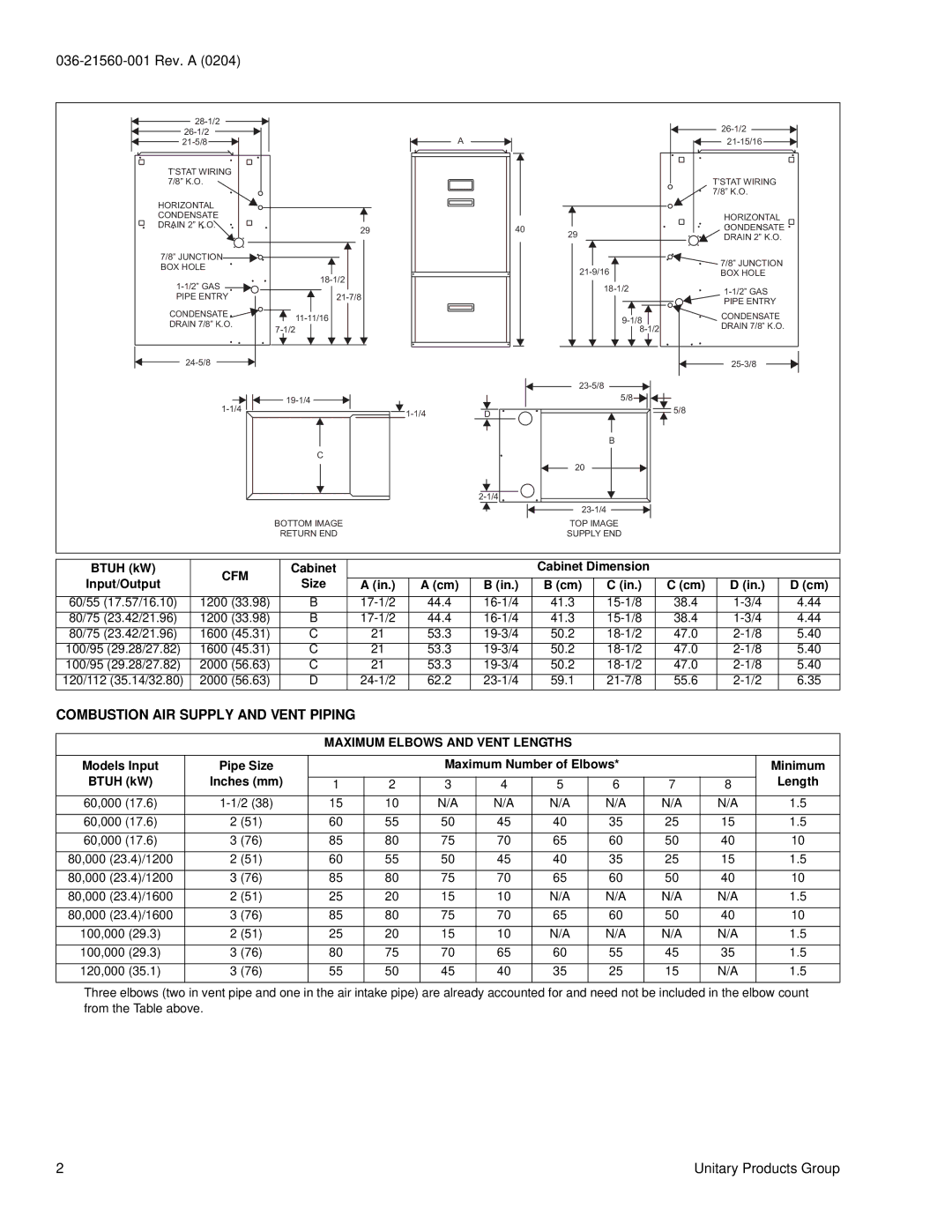
Three elbows (two in vent pipe and one in the air intake pipe) are already accounted for and need not be included in the elbow count from the Table above.

2

Unitary Products Group

Page 2
Image 2
York GY9 warranty Combustion AIR Supply and Vent Piping, Input/Output Size, Maximum Elbows and Vent Lengths

GY9 specifications

York GY9, GF9, and GM9 are advanced air conditioning units known for their efficiency and innovative technology. Designed primarily for commercial and industrial applications, these units are engineered to provide optimal performance while minimizing energy consumption.

One of the main features of the York GY9 series is its scroll compressor technology. This design is renowned for its reliability and quiet operation. The scroll compressors operate in a manner that reduces vibration and noise, making them suitable for environments where minimal disruption is crucial. Furthermore, these compressors are designed to optimize refrigerant circulation, contributing to improved cooling efficiency.

The GF9 model, on the other hand, is characterized by its modular design, which allows for easy scalability. This feature is particularly beneficial for businesses looking to expand their cooling capacity without extensive renovations. The modular approach means that multiple units can be connected and controlled as a single system, providing flexibility in design and installation.

In terms of energy efficiency, all three models integrate the latest environmentally-friendly refrigerants. These refrigerants help reduce the overall carbon footprint of the HVAC system while maintaining effective cooling performance. The units are designed to meet or exceed industry standards for energy efficiency, making them a cost-effective choice for long-term use.

Another notable characteristic of the York GY9, GF9, and GM9 units is their user-friendly control systems. Advanced control options include smart thermostats and building management system integration, allowing users to monitor and fine-tune their cooling performance remotely. This level of control enhances convenience and can lead to further energy savings through optimized operation.

Durability is also a key feature of these models. Constructed with robust materials, the York GY9, GF9, and GM9 are designed to withstand various environmental conditions, ensuring longevity and reducing maintenance costs. Their designs also incorporate advanced filtration systems, which improve indoor air quality by effectively removing pollutants and allergens.

In summary, York GY9, GF9, and GM9 air conditioning units stand out due to their efficient cooling, innovative technologies, energy-saving features, and robust construction. These units are ideal for commercial settings looking to balance performance with sustainability, all while ensuring a comfortable environment.