|
|
|
|
| ||
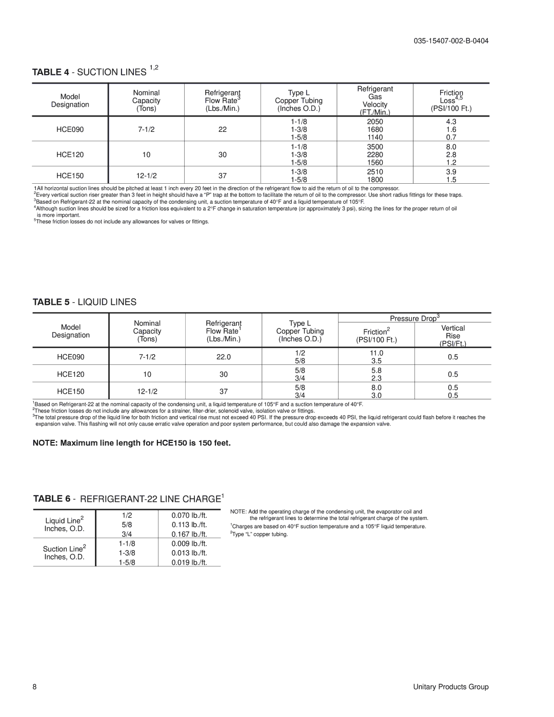
TABLE 4 - SUCTION LINES 1,2 |
|
|
|
| ||
|
|
|
|
|
| |
| Nominal | Refrigerant | Type L | Refrigerant | Friction | |
Model | Gas | |||||
Capacity | Flow Rate3 | Copper Tubing | Loss4,5 | |||
Designation | (Tons) | (Lbs./Min.) | (Inches O.D.) | Velocity | (PSI/100 Ft.) | |
| (FT./Min.) | |||||
|
|
|
|
| ||
|
|
| 2050 | 4.3 | ||
HCE090 | 22 | 1680 | 1.6 | |||
|
|
| 1140 | 0.7 | ||
|
|
| 3500 | 8.0 | ||
HCE120 | 10 | 30 | 2280 | 2.8 | ||
|
|
| 1560 | 1.2 | ||
HCE150 | 37 | 2510 | 3.9 | |||
1800 | 1.5 | |||||
|
|
| ||||
1All horizontal suction lines should be pitched at least 1 inch every 20 feet in the direction of the refrigerant flow to aid the return of oil to the compressor.
2Every vertical suction riser greater than 3 feet in height should have a “P” trap at the bottom to facilitate the return of oil to the compressor. Use short radius fittings for these traps. 3Based on
4Although suction lines should be sized for a friction loss equivalent to a 2°F change in saturation temperature (or approximately 3 psi), sizing the lines for the proper return of oil is more important.
5These friction losses do not include any allowances for valves or fittings.
TABLE 5 - LIQUID LINES
Model | Nominal | Refrigerant | Type L |
| Pressure Drop3 | |
Capacity | Flow Rate1 | Copper Tubing | Friction2 |
| Vertical | |
Designation | (Tons) | (Lbs./Min.) | (Inches O.D.) | (PSI/100 Ft.) | Rise | |
| (PSI/Ft.) | |||||
|
|
|
|
|
| |
HCE090 | 22.0 | 1/2 | 11.0 |
| 0.5 | |
5/8 | 3.5 |
| ||||
|
|
|
|
| ||
HCE120 | 10 | 30 | 5/8 | 5.8 |
| 0.5 |
3/4 | 2.3 |
| ||||
|
|
|
|
| ||
HCE150 | 37 | 5/8 | 8.0 |
| 0.5 | |
3/4 | 3.0 |
| 0.5 | |||
|
|
|
| |||
1Based on
2These friction losses do not include any allowances for a strainer,
3The total pressure drop of the liquid line for both friction and vertical rise must not exceed 40 PSI. If the pressure drop exceeds 40 PSI, the liquid refrigerant could flash before it reaches the expansion valve. This flashing will not only cause erratic valve operation and poor system performance, but could also damage the expansion valve.
NOTE: Maximum line length for HCE150 is 150 feet.
TABLE 6 - REFRIGERANT-22 LINE CHARGE1
Liquid Line2 | 1/2 | 0.070 lb./ft. | |
5/8 | 0.113 lb./ft. | ||
Inches, O.D. | |||
3/4 | 0.167 lb./ft. | ||
| |||
Suction Line2 | 0.009 lb./ft. | ||
0.013 lb./ft. | |||
Inches, O.D. | |||
0.019 lb./ft. | |||
|
NOTE: Add the operating charge of the condensing unit, the evaporator coil and the refrigerant lines to determine the total refrigerant charge of the system.
1Charges are based on 40°F suction temperature and a 105°F liquid temperature.
2Type “L” copper tubing.
8 | Unitary Products Group |