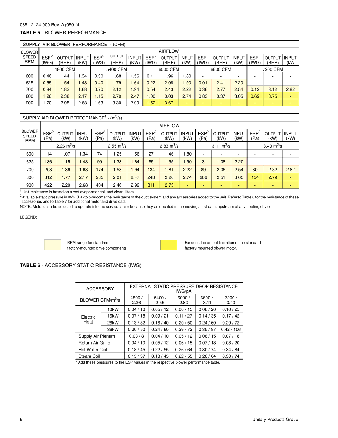
TABLE 5 - BLOWER PERFORMANCE
SUPPLY AIR BLOWER PERFORMANCE1 - (CFM)
BLOWER |
|
|
|
|
|
|
|
| AIRFLOW |
|
|
|
|
|
|
|
SPEED |
| ESP2 | OUTPUT | INPUT | ESP2 | OUTPUT | INPUT | ESP2 | OUTPUT | INPUT | ESP2 | OUTPUT | INPUT | ESP2 | OUTPUT | INPUT |
RPM |
| (IWG) | (BHP) | (kW) | (IWG) | (BHP) | (KW) | (IWG) | (BHP) | (kW) | (IWG) | (BHP) | (kW) | (IWG) | (BHP) | (kW |
|
|
| 4800 CFM |
|
| 5400 CFM |
|
| 6000 CFM |
|
| 6600 CFM |
|
| 7200 CFM |
|
600 | 0.46 | 1.44 | 1.34 | 0.30 | 1.68 | 1.56 | 0.11 | 1.96 | 1.80 | - | - | - | - | - | - | |
625 | 0.55 | 1.54 | 1.43 | 0.40 | 1.79 | 1.64 | 0.22 | 2.08 | 1.90 | 0.01 | 2.41 | 2.20 | - | - | - | |
700 | 0.84 | 1.83 | 1.68 | 0.70 | 2.12 | 1.94 | 0.54 | 2.43 | 2.22 | 0.36 | 2.77 | 2.54 | 0.12 | 3.12 | 2.82 | |
800 | 1.26 | 2.38 | 2.17 | 1.15 | 2.70 | 2.47 | 1.00 | 3.03 | 2.74 | 0.83 | 3.37 | 3.05 | 0.62 | 3.75 | - | |
900 | 1.70 | 2.95 | 2.68 | 1.63 | 3.30 | 2.99 | 1.52 | 3.67 | - | - | - | - | - | - | - | |
|
|
|
|
|
|
|
|
|
|
|
|
|
|
|
| |
SUPPLY AIR BLOWER PERFORMANCE1 - (m3/s) |
|
|
|
|
|
|
|
|
|
| ||||||
|
|
|
|
|
|
|
|
| AIRFLOW |
|
|
|
|
|
|
|
BLOWER |
|
|
|
|
|
|
|
|
|
|
|
|
|
|
|
|
| ESP2 | OUTPUT | INPUT | ESP2 | OUTPUT | INPUT | ESP2 | OUTPUT | INPUT | ESP2 | OUTPUT | INPUT | ESP2 | OUTPUT | INPUT | |
SPEED |
| (Pa) | (kW) | (kW) | (Pa) | (kW) | (kW) | (Pa) | (kW) | (kW) | (Pa) | (kW) | (kW) | (Pa) | (kW) | (kW) |
RPM |
| |||||||||||||||
|
|
|
|
|
|
|
|
|
|
|
|
|
|
|
| |
|
| 2.26 m3/s |
|
| 2.55 m3/s |
|
| 2.83 m3/s |
|
| 3.11 m3/s |
|
| 3.40 m3/s |
| |
|
|
|
|
|
|
|
|
|
|
|
| |||||
600 |
| 114 | 1.07 | 1.34 | 74 | 1.25 | 1.56 | 27 | 1.46 | 1.80 | - | - | - | - | - | - |
|
|
|
|
|
|
|
|
|
|
|
|
|
|
|
|
|
625 |
| 136 | 1.15 | 1.43 | 99 | 1.33 | 1.64 | 55 | 1.55 | 1.90 | 3 | 1.08 | 2.20 | - | - | - |
700 |
| 208 | 1.36 | 1.68 | 174 | 1.58 | 1.94 | 134 | 1.81 | 2.22 | 89 | 2.06 | 2.54 | 30 | 2.32 | 2.82 |
800 |
| 312 | 1.77 | 2.17 | 285 | 2.01 | 2.47 | 248 | 2.26 | 2.74 | 206 | 2.51 | 3.05 | 154 | 2.79 | - |
900 |
| 422 | 2.20 | 2.68 | 404 | 2.46 | 2.99 | 311 | 2.73 | - | - | - | - | - | - | - |
|
|
|
|
|
|
|
|
|
|
|
|
|
|
|
|
|
1Unit resistance is based on a wet evaporator coil and clean filters.
2Available static pressure in IWG (Pa) to overcome the resistance of the duct system and any accessories added to the unit. Refer to Table 6 for the resistance of these accessories and to Table 7 for additional motor and drive data
NOTE: Motors can be selected to operate into the service factor because they are located in the moving air stream, upstream of any heating device.
LEGEND:
RPM range for standard
Exceeds the output limitation of the standard
TABLE 6 - ACCESSORY STATIC RESISTANCE (IWG)
ACCESSORY | EXTERNAL STATIC PRESSURE DROP RESISTANCE | ||||||
|
| IWG/pA |
|
| |||
|
|
|
|
|
|
| |
BLOWER CFM/m3/s | 4800 / | 5400 / | 6000 / | 6600 / | 7200 / | ||
|
|
| 2.26 | 2.55 | 2.83 | 3.11 | 3.40 |
|
| 10kW | 0.04 / 10 | 0.05 / 12 | 0.06 / 15 | 0.08 / 20 | 0.10 / 25 |
Electric |
| 16kW | 0.07 / 18 | 0.09 / 21 | 0.11 / 27 | 0.14 / 35 | 0.17 / 42 |
Heat |
| 26kW | 0.13 / 32 | 0.16 / 40 | 0.20 / 50 | 0.24 / 60 | 0.29 / 72 |
|
| 36kW | 0.20 / 50 | 0.24 / 60 | 0.29 / 72 | 0.35 / 87 | 0.42 / 106 |
Supply Air Plenum | 0.03 / 8 | 0.04 / 10 | 0.05 / 12 | 0.06 / 15 | 0.07 / 18 | ||
Return Air Grille | 0.04 / 10 | 0.05 / 12 | 0.06 / 15 | 0.07 / 18 | 0.08 / 20 | ||
Hot Water Coil |
| 0.18 / 45 | 0.22 / 55 | 0.26 / 64 | 0.30 / 74 | 0.34 / 84 | |
Steam Coil |
| 0.15 / 37 | 0.18 / 45 | 0.22 / 55 | 0.26 / 64 | 0.30 / 74 | |
* Add these pressures to the ESP values in the respective blower performance table.
6 | Unitary Products Group |