


 LD03226
  LD03227
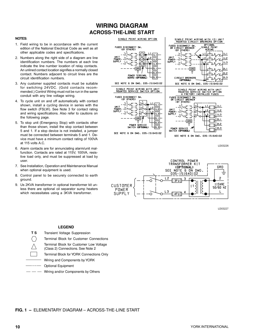
YCAS0230 specifications
The York YCAS0230 is a highly efficient air conditioning unit that showcases cutting-edge technology and innovative design suitable for commercial and industrial applications. With its robust engineering, the YCAS0230 is built to handle substantial cooling demands while ensuring energy efficiency and sustainability.One of the standout features of the YCAS0230 is its advanced scroll compressor. This mechanism not only provides reliable performance but also reduces energy consumption significantly. The unit operates quietly, making it an ideal solution for environments where noise reduction is a priority. Additionally, the scroll design contributes to the longevity of the compressor, providing durability and reduced maintenance costs over time.
Another defining characteristic of the YCAS0230 is its use of environmentally-friendly refrigerants, which comply with the latest regulations regarding ozone depletion and global warming potential. By utilizing these refrigerants, the YCAS0230 not only ensures efficient cooling but also aligns with modern standards of ecological responsibility, catering to businesses looking to improve their sustainability credentials.
The YCAS0230 also features advanced control systems that allow for precise management of the unit's operation. These controls offer multiple modes of operation, which can be programmed to adapt to different cooling needs and schedules. This flexibility enhances user experience and maximizes energy savings, making the unit not just efficient but also user-friendly.
In terms of design, the YCAS0230 is compact and lightweight, facilitating easy installation and integration into existing systems. Its weather-resistant cabinet ensures reliable performance even in adverse conditions, making it suitable for outdoor installations. The unit is designed with accessibility in mind, allowing for straightforward maintenance and servicing.
Additionally, the YCAS0230 integrates seamlessly with various building management systems. This compatibility allows for centralized control and monitoring, providing facility managers with valuable insights into energy usage and operational performance.
In summary, the York YCAS0230 merges modern technology with user-centered features, resulting in an air conditioning unit that delivers exceptional performance, reliability, and eco-friendliness. Its combination of advanced compressors, responsible refrigerants, and smart controls positions it as a leading choice for businesses looking to invest in efficient climate control solutions.