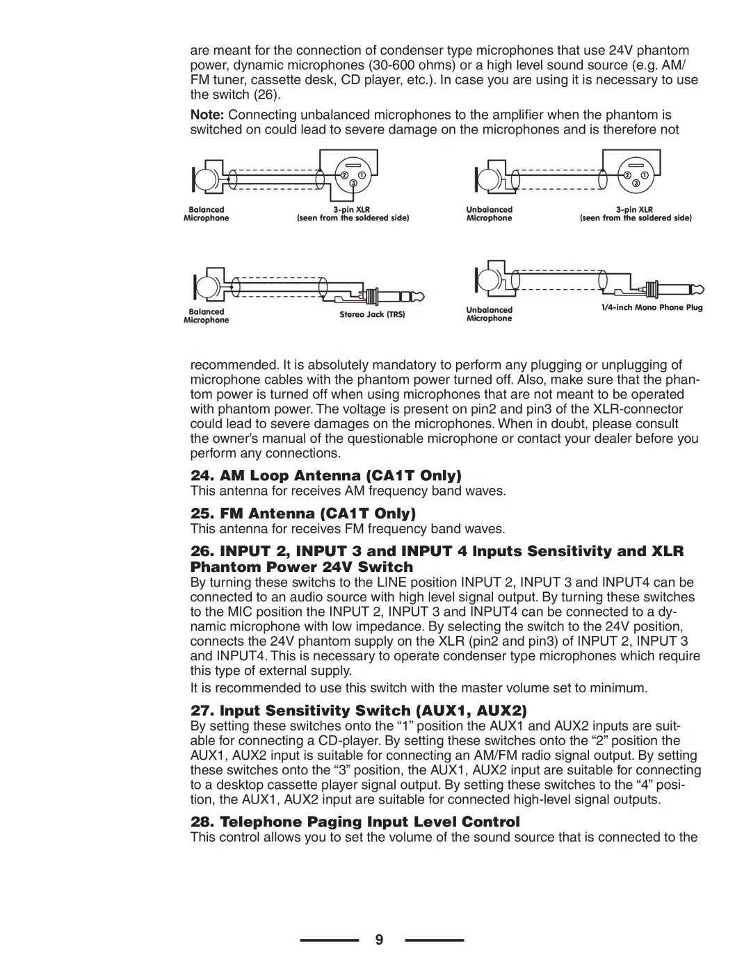
are meant for the connection of condenser type microphones that use 24V phantom power, dynamic microphones
Note: Connecting unbalanced microphones to the amplifier when the phantom is switched on could lead to severe damage on the microphones and is therefore not
21
3
21
3
Balanced |
|
| Unbalanced |
|
|
|
| ||||||||||||||||||||||||||||||||
Microphone | (seen from the soldered side) | Microphone |
| (seen from the soldered side) | |||||||||||||||||||||||||||||||||||
|
|
|
|
|
|
|
|
|
|
|
|
|
|
|
|
|
|
|
|
|
|
|
|
|
|
|
|
|
|
|
|
|
|
|
|
|
|
|
|
|
|
|
|
|
|
|
|
|
|
|
|
|
|
|
|
|
|
|
|
|
|
|
|
|
|
|
|
|
|
|
|
|
|
|
|
|
|
|
|
Balanced |
|
|
| Unbalanced | ||
Stereo Jack (TRS) | ||||||
| ||||||
Microphone |
|
|
| Microphone |
| |
recommended. It is absolutely mandatory to perform any plugging or unplugging of microphone cables with the phantom power turned off. Also, make sure that the phan- tom power is turned off when using microphones that are not meant to be operated with phantom power. The voltage is present on pin2 and pin3 of the
24. AM Loop Antenna (CA1T Only)
This antenna for receives AM frequency band waves.
25. FM Antenna (CA1T Only)
This antenna for receives FM frequency band waves.
26.INPUT 2, INPUT 3 and INPUT 4 lnputs Sensitivity and XLR Phantom Power 24V Switch
By turning these switchs to the LINE position INPUT 2, INPUT 3 and INPUT4 can be connected to an audio source with high level signal output. By turning these switches to the MIC position the INPUT 2, INPUT 3 and INPUT4 can be connected to a dy- namic microphone with low impedance. By selecting the switch to the 24V position, connects the 24V phantom supply on the XLR (pin2 and pin3) of INPUT 2, INPUT 3 and INPUT4. This is necessary to operate condenser type microphones which require this type of external supply.
It is recommended to use this switch with the master volume set to minimum.
27.lnput Sensitivity Switch (AUX1, AUX2)
By setting these switches onto the “1” position the AUX1 and AUX2 inputs are suit- able for connecting a
28. Telephone Paging Input Level Control
This control allows you to set the volume of the sound source that is connected to the
9