 mc12d
mc12d
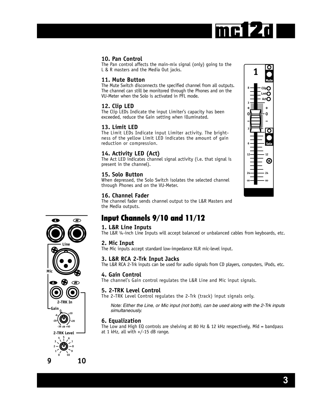
10. Pan Control
The Pan control affects the
11. Mute Button
The Mute Switch disconnects the specified channel from all outputs. The channel can still be monitored through the Phones and on the
1
Mute
8Clip![]() Lmt
Lmt![]()
3
Act![]()
12. Clip LED
The Clip LEDs Indicate the input Limiter’s capacity has been exceeded, reduce the Gain setting when illuminated.
13. Limit LED
The Limit LEDs Indicate input Limiter activity. The bright- ness of the yellow Limit LED indicates the amount of gain reduction or compression.
14. Activity LED (Act)
The Act LED indicates channel signal activity (i.e. that signal is present in the channel).
15. Solo Button
When depressed, the Solo Switch isolates the selected channel through Phones and on the
+ ![]()
![]()
![]()
![]()
![]() +
+
0 | 0 |
- | - |
3 |
6Solo
12 12
24 24
0 0 |
|
|
| 0 0 |
|
|
Line
Mic
Gain 0
4 5 6
37
28
19
9 0 10 10
16. Channel Fader
The channel fader sends channel output to the L&R Masters and the Media outputs.
Input Channels 9/10 and 11/12
1. L&R Line Inputs
The L&R
2. Mic Input
The Mic inputs accept standard
3. L&R RCA
The L&R RCA
4. Gain Control
The channel’s Gain control regulates the L&R Line and Mic input signals.
5.
The
Note: Either the Line, or Mic input (not both), can be used along with the
6. Equalization
The Low and High EQ controls are shelving at 80 Hz & 12 kHz respectively, Mid = bandpass at 1 kHz, all with
3
