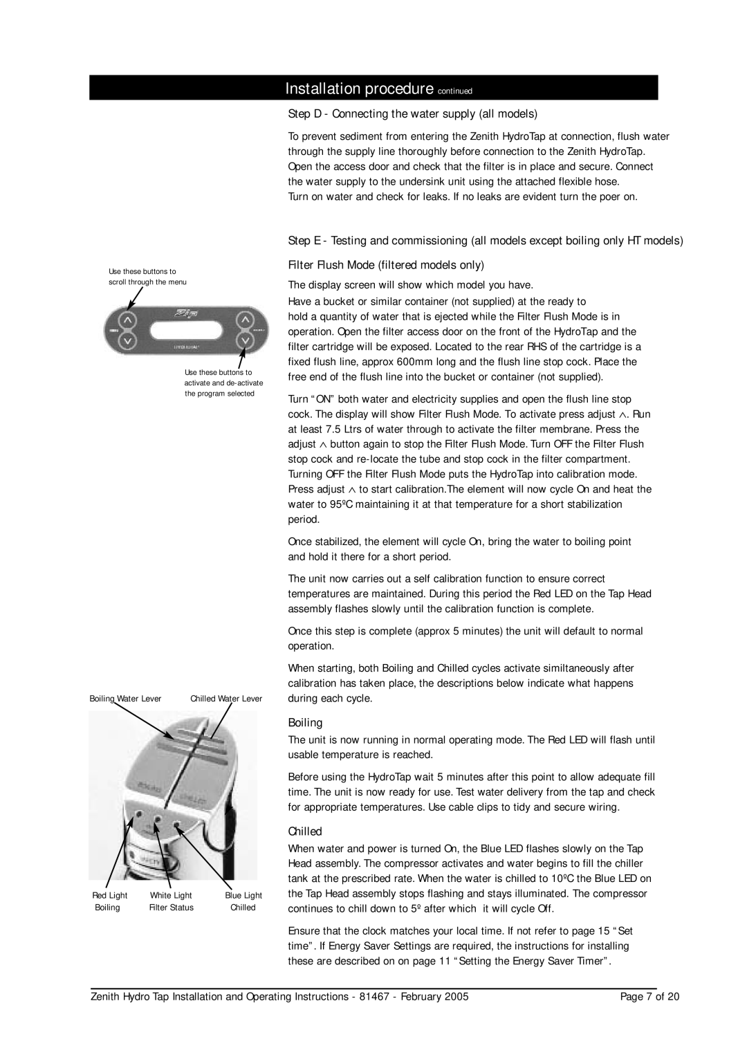
Use these buttons to scroll through the menu
Use these buttons to activate and
Boiling Water Lever | Chilled Water Lever |
Red Light | White Light | Blue Light |
Boiling | Filter Status | Chilled |
Installation procedure continued
Step D - Connecting the water supply (all models)
To prevent sediment from entering the Zenith HydroTap at connection, flush water through the supply line thoroughly before connection to the Zenith HydroTap. Open the access door and check that the filter is in place and secure. Connect the water supply to the undersink unit using the attached flexible hose.
Turn on water and check for leaks. If no leaks are evident turn the poer on.
Step E - Testing and commissioning (all models except boiling only HT models)
Filter Flush Mode (filtered models only)
The display screen will show which model you have.
Have a bucket or similar container (not supplied) at the ready to
hold a quantity of water that is ejected while the Filter Flush Mode is in operation. Open the filter access door on the front of the HydroTap and the filter cartridge will be exposed. Located to the rear RHS of the cartridge is a fixed flush line, approx 600mm long and the flush line stop cock. Place the free end of the flush line into the bucket or container (not supplied).
Turn “ON” both water and electricity supplies and open the flush line stop cock. The display will show Filter Flush Mode. To activate press adjust ∧. Run at least 7.5 Ltrs of water through to activate the filter membrane. Press the adjust ∧ button again to stop the Filter Flush Mode. Turn OFF the Filter Flush stop cock and
Once stabilized, the element will cycle On, bring the water to boiling point and hold it there for a short period.
The unit now carries out a self calibration function to ensure correct temperatures are maintained. During this period the Red LED on the Tap Head assembly flashes slowly until the calibration function is complete.
Once this step is complete (approx 5 minutes) the unit will default to normal operation.
When starting, both Boiling and Chilled cycles activate similtaneously after calibration has taken place, the descriptions below indicate what happens during each cycle.
Boiling
The unit is now running in normal operating mode. The Red LED will flash until usable temperature is reached.
Before using the HydroTap wait 5 minutes after this point to allow adequate fill time. The unit is now ready for use. Test water delivery from the tap and check for appropriate temperatures. Use cable clips to tidy and secure wiring.
Chilled
When water and power is turned On, the Blue LED flashes slowly on the Tap Head assembly. The compressor activates and water begins to fill the chiller tank at the prescribed rate. When the water is chilled to 10ºC the Blue LED on the Tap Head assembly stops flashing and stays illuminated. The compressor continues to chill down to 5º after which it will cycle Off.
Ensure that the clock matches your local time. If not refer to page 15 “Set time”. If Energy Saver Settings are required, the instructions for installing these are described on on page 11 “Setting the Energy Saver Timer”.
Zenith Hydro Tap Installation and Operating Instructions - 81467 - February 2005 | Page 7 of 20 |