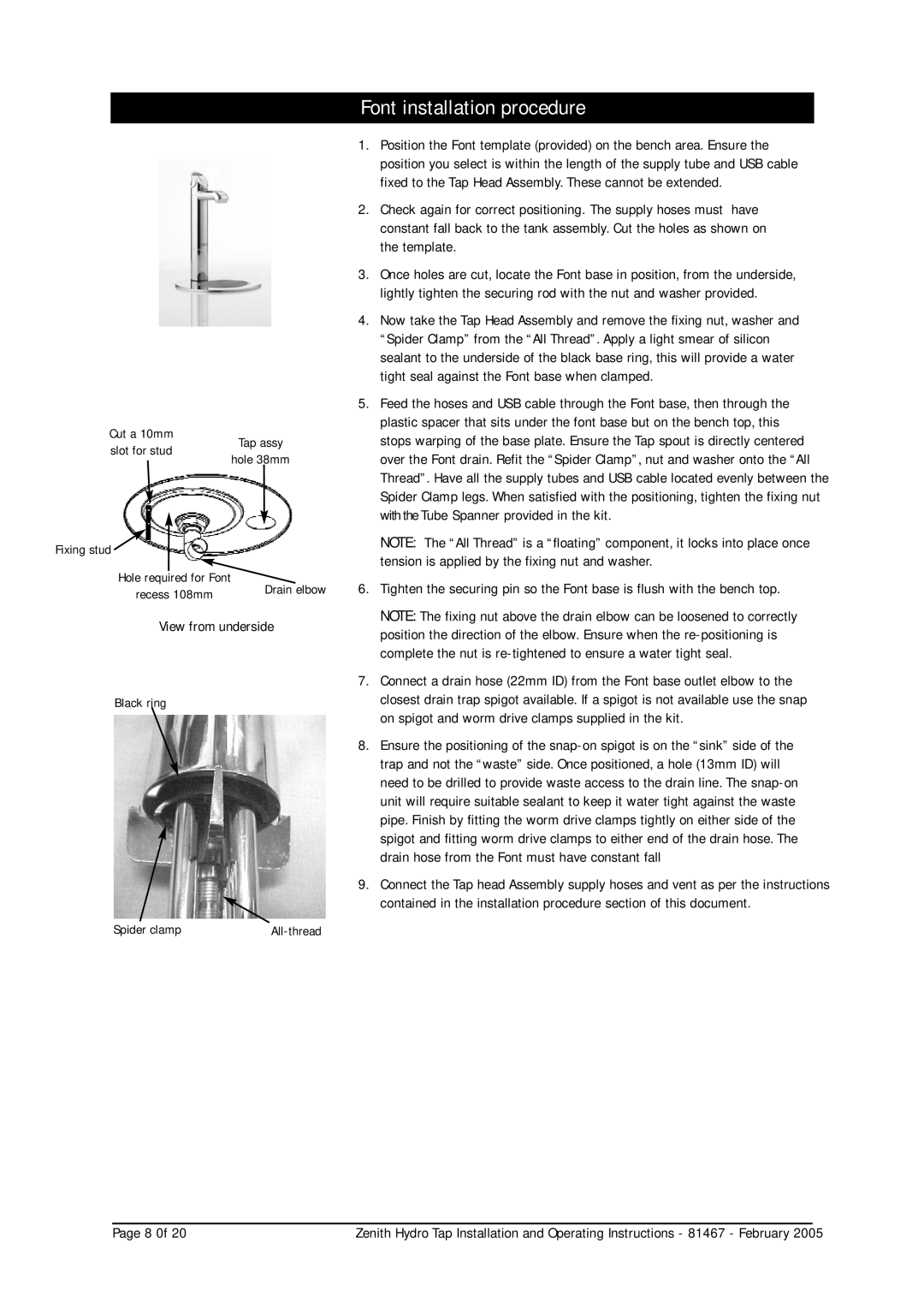
Cut a 10mm
Font installation procedure
1. | Position the Font template (provided) on the bench area. Ensure the |
| position you select is within the length of the supply tube and USB cable |
| fixed to the Tap Head Assembly. These cannot be extended. |
2. | Check again for correct positioning. The supply hoses must have |
| constant fall back to the tank assembly. Cut the holes as shown on |
| the template. |
3. | Once holes are cut, locate the Font base in position, from the underside, |
| lightly tighten the securing rod with the nut and washer provided. |
4. | Now take the Tap Head Assembly and remove the fixing nut, washer and |
| “Spider Clamp” from the “All Thread”. Apply a light smear of silicon |
| sealant to the underside of the black base ring, this will provide a water |
| tight seal against the Font base when clamped. |
5. | Feed the hoses and USB cable through the Font base, then through the |
| plastic spacer that sits under the font base but on the bench top, this |
slot for stud
Tap assy
stops warping of the base plate. Ensure the Tap spout is directly centered |
hole 38mm
Fixing stud ![]()
Hole required for Font
recess 108mm | Drain elbow |
| |
View from underside | |
Black ring
LARGE HOLE
Spider clamp |
over the Font drain. Refit the “Spider Clamp”, nut and washer onto the “All |
Thread”. Have all the supply tubes and USB cable located evenly between the |
Spider Clamp legs. When satisfied with the positioning, tighten the fixing nut |
with the Tube Spanner provided in the kit. |
NOTE: The “All Thread” is a “floating” component, it locks into place once |
tension is applied by the fixing nut and washer. |
6. Tighten the securing pin so the Font base is flush with the bench top. |
NOTE: The fixing nut above the drain elbow can be loosened to correctly |
position the direction of the elbow. Ensure when the |
complete the nut is |
7. Connect a drain hose (22mm ID) from the Font base outlet elbow to the |
closest drain trap spigot available. If a spigot is not available use the snap |
on spigot and worm drive clamps supplied in the kit. |
8. Ensure the positioning of the |
trap and not the “waste” side. Once positioned, a hole (13mm ID) will |
need to be drilled to provide waste access to the drain line. The |
unit will require suitable sealant to keep it water tight against the waste |
pipe. Finish by fitting the worm drive clamps tightly on either side of the |
spigot and fitting worm drive clamps to either end of the drain hose. The |
drain hose from the Font must have constant fall |
9. Connect the Tap head Assembly supply hoses and vent as per the instructions |
contained in the installation procedure section of this document. |
Page 8 0f 20 | Zenith Hydro Tap Installation and Operating Instructions - 81467 - February 2005 |