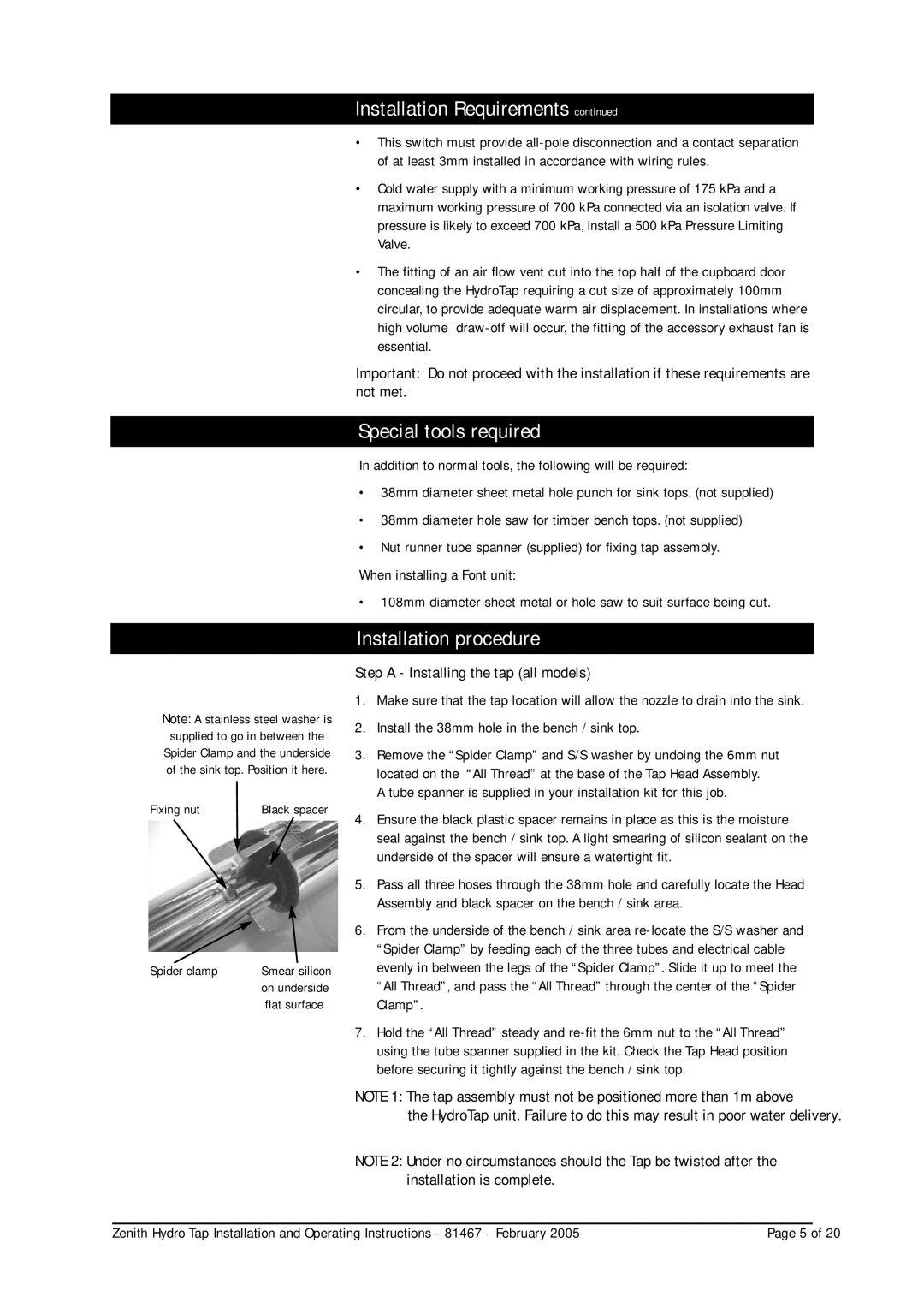
Note: A stainless steel washer is supplied to go in between the Spider Clamp and the underside of the sink top. Position it here.
Fixing nut | Black spacer |
Spider clamp | Smear silicon |
| on underside |
| flat surface |
Installation Requirements continued
•This switch must provide
•Cold water supply with a minimum working pressure of 175 kPa and a maximum working pressure of 700 kPa connected via an isolation valve. If pressure is likely to exceed 700 kPa, install a 500 kPa Pressure Limiting Valve.
•The fitting of an air flow vent cut into the top half of the cupboard door concealing the HydroTap requiring a cut size of approximately 100mm circular, to provide adequate warm air displacement. In installations where high volume
Important: Do not proceed with the installation if these requirements are not met.
Special tools required
In addition to normal tools, the following will be required:
•38mm diameter sheet metal hole punch for sink tops. (not supplied)
•38mm diameter hole saw for timber bench tops. (not supplied)
•Nut runner tube spanner (supplied) for fixing tap assembly.
When installing a Font unit:
• 108mm diameter sheet metal or hole saw to suit surface being cut.
Installation procedure
Step A - Installing the tap (all models)
1.Make sure that the tap location will allow the nozzle to drain into the sink.
2.Install the 38mm hole in the bench / sink top.
3.Remove the “Spider Clamp” and S/S washer by undoing the 6mm nut located on the “All Thread” at the base of the Tap Head Assembly.
A tube spanner is supplied in your installation kit for this job.
4.Ensure the black plastic spacer remains in place as this is the moisture seal against the bench / sink top. A light smearing of silicon sealant on the underside of the spacer will ensure a watertight fit.
5.Pass all three hoses through the 38mm hole and carefully locate the Head Assembly and black spacer on the bench / sink area.
6.From the underside of the bench / sink area
7.Hold the “All Thread” steady and
NOTE 1: The tap assembly must not be positioned more than 1m above
the HydroTap unit. Failure to do this may result in poor water delivery.
NOTE 2: Under no circumstances should the Tap be twisted after the installation is complete.
Zenith Hydro Tap Installation and Operating Instructions - 81467 - February 2005 | Page 5 of 20 |