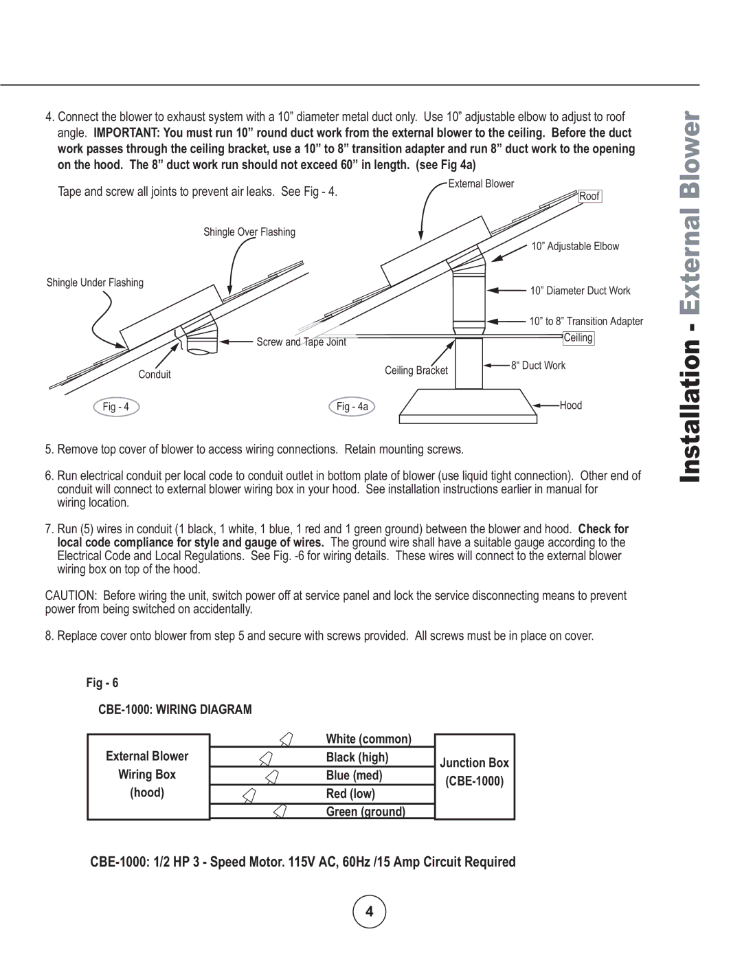
4.Connect the blower to exhaust system with a 10” diameter metal duct only. Use 10” adjustable elbow to adjust to roof angle. IMPORTANT: You must run 10” round duct work from the external blower to the ceiling. Before the duct work passes through the ceiling bracket, use a 10” to 8” transition adapter and run 8” duct work to the opening on the hood. The 8” duct work run should not exceed 60” in length. (see Fig 4a)
Blower
Tape and screw all joints to prevent air leaks. See Fig - 4.
Shingle Over Flashing
External Blower
Roof
Shingle Under Flashing
Screw and Tape Joint
Conduit
Ceiling Bracket
10” Adjustable Elbow
10” Diameter Duct Work
![]() 10” to 8” Transition Adapter
10” to 8” Transition Adapter
Ceiling
![]() 8“ Duct Work
8“ Duct Work
Fig - 4 | Fig - 4a | Hood |
5.Remove top cover of blower to access wiring connections. Retain mounting screws.
6.Run electrical conduit per local code to conduit outlet in bottom plate of blower (use liquid tight connection). Other end of conduit will connect to external blower wiring box in your hood. See installation instructions earlier in manual for
wiring location.
7.Run (5) wires in conduit (1 black, 1 white, 1 blue, 1 red and 1 green ground) between the blower and hood. Check for local code compliance for style and gauge of wires. The ground wire shall have a suitable gauge according to the Electrical Code and Local Regulations. See Fig.
CAUTION: Before wiring the unit, switch power off at service panel and lock the service disconnecting means to prevent power from being switched on accidentally.
8. Replace cover onto blower from step 5 and secure with screws provided. All screws must be in place on cover.
Installation - External
Fig - 6
CBE-1000: WIRING DIAGRAM
External Blower | White (common) |
Black (high) | |
Wiring Box | Blue (med) |
(hood) | Red (low) |
| Green (ground) |
Junction Box
4
