negative battery cable. Block up mower when you must work under it. Wear gloves when handling blades. Always check for blade damage if mower strikes rock, branch or other foreign object during mowing!
WARNING: Always wear adequate eye protection when grinding mower blades.
Always place deck clutch switch in the disengaged position, place control levers in the park brake position and turn engine off and disconnect negative battery cable. Block up mower when you must work under it. Wear gloves when handling blades. Always check for blade damage if mower strikes rock, branch or other foreign object during mowing!
Mower blade removal
Use a 15/16" wrench to remove the 5/8" cap screw holding the blade to the spindle shaft from underneath. NOTE: A blade holding tool (part number 381442) is available from Hustler Turf Equipment. It is designed to prevent the blades from rotating when they are being removed or installed on the spindle. Contact your Hustler dealer for more information.
Sharpen the blades on a grinder following pattern as shown (Fig.
Check the blades for balance following grinding. A commercial balancing tool is available through most hardware supply stores, or balancing can be done by placing the blade on an inverted line punch or 5/8" bolt. Blade should not lean or tilt. Spin the blade slowly, blade should not wobble. If blade is out of balance, true it up before reinstalling.
Lay the blade on a flat surface and check for distortion (Fig.
Do not
IMPORTANT: The blade sail (curved part) must be pointing upward toward the inside of the deck to ensure proper cutting.
WARNING: When mounting blades, rotate them after installation to ensure blade tips do not touch each other or sides of the mower.
WARNING: Failure to correctly torque the bolt may result in the loss of the blade which can cause serious injury.
WARNING: Mower blades are sharp and can cut. Wrap the blade(s) or wear gloves and use extra caution when servicing them.
Seat adjustment
The seat can be adjusted forward and rearward by removing the locknut that locks the seat platform in place and pivoting the seat platform up and forward. Then loosen the four cap screws on the underneath side of the operator’s platform. Position the seat where you have the best control of the machine and are the most comfortable and then tighten the cap screws. Fig.
Control lever adjustment
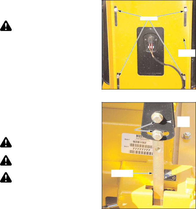
The steering control levers can be adjusted for operator comfort. By loosening the cap screws that attaches the upper control lever to the lower lever (Fig.
The steering control levers can also be adjusted up and down. Remove the cap screws and slide the upper control lever up or down and align the holes in it with the holes in lower lever.
The steering control levers should be adjusted so that they align with each other when in the neutral position.
Cap screw
Operator’s
platform
Figure
Upper ![]() control lever
control lever
Cap screw
Lower control
lever
Figure
107708_0808 | 23 |