Star Micronics TSP400 technical manual Editing and Printing

Page 28

THEORY OF OPERATION

2-2. Editing and Printing

2-2-1. Editing

The CPU reads data sequentially from RAM and edits it in accordance with program instructions stored in EPROM. The edited data undergoes parallel-to-serial conversion in the gate array, and is then output to the thermal head’s drive controller.

2-2-2. Thermal head

The thermal head contains 640 heat elements. Printing is carried out by switching these elements ON or OFF as required.

Note that Line Mode supports 600-dot printing only. During Line Mode operation, therefore, the logic always sends OFF data to elements 1 to 20 and 621 to 640.

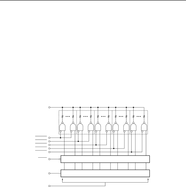
The thermal head contains a dedicated drive controller. The controller consists of a shift register, a latch circuit, and a driver circuit, as illustrated below. The drive controller receives serial data (SI) from the drive control board in sync with the CLOCK signal. The controller latches the incoming data (LATCH), then outputs it to the heat elements in sync with the trailing edge of the STROBE signals. A data value of LOW corresponds to a heat-element value of ON.

COM

STROBE5

STROBE4

STROBE3

STROBE2

STROBE1

LATCH

Latch

SI

Shift Register

CLOCK

Fig. 2-5 Thermal-Head Drive Circuit

– 24 –

Image 28
Contents TSP400 Series Page Introduction Page Chapter Specifications and Operation Specifications and Operation General Specifications OCR-BExternal Appearance and Internal Configuration Internal Configuration TSP412DDIP-Switch Settings Status of printer power Baud Print-Density Adjustment Sensor Adjustment Specifications and Operation Setting Memory Switches from the Control Panel Test Print HEX DumpPage/Line Mode Switch Exposing the Peripheral Unit Connector Changing the Interface Board Specifications and Operation Chapter Theory of Operation Theory of Operation Block Diagram 24VControl Panel Main and Interface PCBs Interface2. RS422A interface Parallel Interface PCB Main PCB Editing and Printing EditingTiming Chart Motor Control by Phase 1-2 Excitation Feed-Motor Drive CircuitPower-On Reset Circuit +5V Line Voltage Detector Circuit 11 Equivalence Circuit for Voltage Detecting ICThermal Head Printer MechanismPaper-Feed Mechanism Detectors 15 Paper-Out Detector19 Head-Up Detector Page Chapter Parts Replacement and Related Adjustments Parts Replacement Upper Casing Unit TSP412DControl-Panel Board Printer Mechanism Main PCB, Interface PCB Power Unit FuseFeed Motor Assembly Printhead unitDetectors Label sensorParts Replacement Chapter Maintenance and Lubrication Maintenance and Lubrication Cleaning MaintenanceChecks Lubrication LubricantsApplication Method Lubrication PointsLubrication Points Maintenance and Lubrication Chapter Parts List Printer Assembly Disassembly DrawingTSP442D Parts List Printer AssemblyScrew TAT Printer Mechanism Assembly Printer Mechanism Oiless Bushing F4X7X3Connector Wiring Diagram RS-232C Interface TypeRS422A I/F Board Control Board Parallel Interface Type Circuit Diagram Main Logic BoardSide a Side D Side C Main Logic Board Chip Resistor 20 K-OHM 1/10W CN8 RS232C Interface RS232C Interface Board RS422A Interface RS422A Interface Board CentronicsInterface Centronics Interface Board Control Panel Board Control Panel Board Paper-Out Detector Board Label Sensor BoardPaper-Out Detector Transmissive SensorPage Distributed by