Installation and Operation, cont’d
NYour YCS may have been shipped with a blue captive screw connector. This blue connector can be plugged into either a blue or an orange power receptacle.
The blue connector does not have the extended tail or the included
CDo not tin the stripped power supply leads before attaching the captive screw plug to them. Tinned wires are not as secure in the captive screw connectors and can be easily pulled out. They may also break after being bent several times.
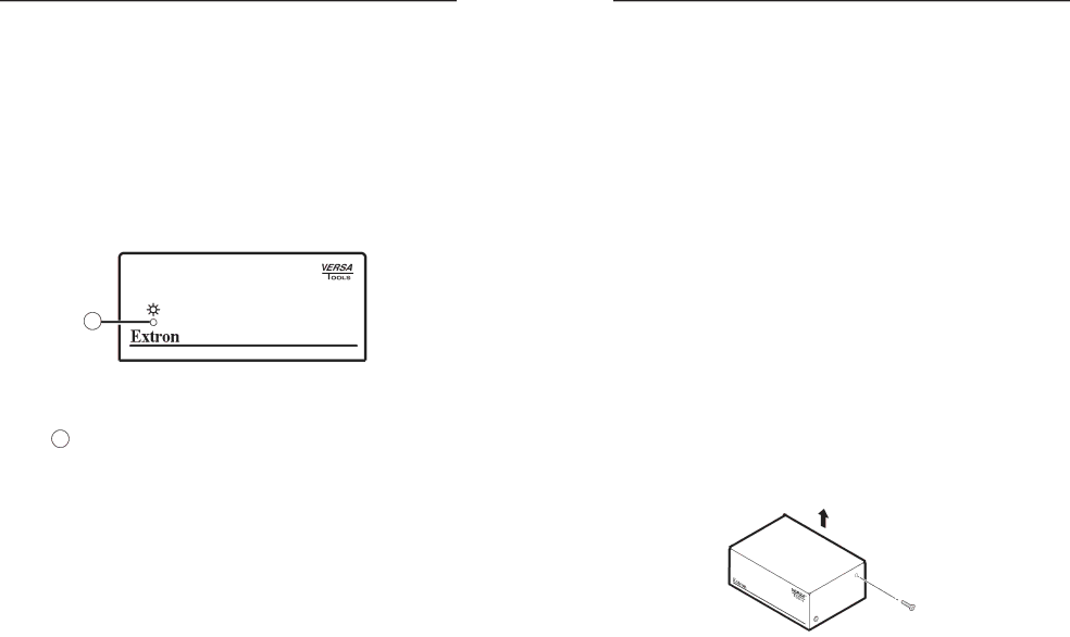
Front Panel
1
YCS 100
VIDEO DECODER/ENCODER
Figure 2-13 — YCS 100 front panel
The YCS 100 front panel contains the following:
1Power LED indicator — This green LED lights when the YCS 100 is receiving power.
Operation
When the transcoder, input sources, and display devices are powered up, the system is fully operational. During YCS 100 operation, one or both of the following takes place:
•The YCS 100 digital decoder accepts a composite video signal and separates it into Y (luma) and C (chroma), converting the signal to output
•The YCS 100 analog encoder accepts an
If problems are encountered, ensure that all cables are routed and connected properly.
Troubleshooting
Possible problems and their solutions include the following:
Problem: No power at unit
Solution: Verify that the unit is receiving power by checking the front panel LED. If the LED is not lit, check the DC power plug termination and polarity.
Problem: No video input
Solution: Verify that the source and output devices are powered on and connected properly.
Problem: Black and white image flashes or scrolls rapidly
Cause: When a black and white signal is used without a colorburst signal, the output image may not sync correctly, causing continual flashing and rapid scrolling of the black and white image.
Solution: Close (enable) the jumper located at CR8 on the YCS 100 internal board. This corrects the black and white picture settings for NTSC and PAL standards.
NWhen you are not using a black and white signal, set the jumper back to the open position (the default).
Follow these steps to enable the jumper:
1. | Disconnect all power to the YCS and any attached devices. |
| If the YCS is mounted, remove it from its mounting. |
2. | Remove the YCS cover by removing the two screws on |
| each side and lifting the cover up and off. |
Lift cover straight up.
Remove (4) screws from sides.
Figure 2-14 — Removing the cover of the YCS 100
3. Locate the
| YCS 100 • Installation and Operation |