Gigabyte GA-K8NF-9-RH Integrated Peripherals, On-Chip IDE Channel0, On-Chip IDE Channel1

Page 34

English

2-3 Integrated Peripherals
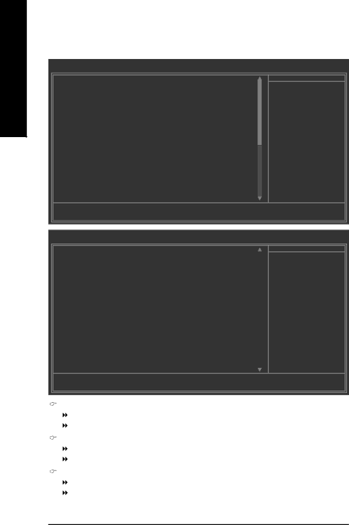
CMOS Setup Utility-Copyright (C) 1984-2006 Award Software

Integrated Peripherals


On-Chip IDE Channel0


[Enabled]


On-Chip IDE Channel1


[Enabled]


IDE DMA transfer access


[Enabled]


On-Chip MAC Lan


[Auto]


On-Chip LAN BOOT ROM


[Enabled]


NV IDE/SATA RAID function

[Disabled]


NV Serial-ATA 1


[Enabled]

x

NV SATA 1 Primary

RAID

Disabled

x

NV SATA 1 Secondary

RAID

Disabled


NV Serial-ATA 2


[Enabled]

x

NV SATA 2 Primary

RAID

Disabled

x

NV SATA 2 Secondary

RAID

Disabled


IDE Prefetch Mode


[Enabled]


USB Memory Type


[SHADOW]


AC97 Audio


[Auto]


Onboard 1394


[Enabled]


Onboard Serial Port 1


[3F8/IRQ4]


Onboard Parallel Port


[378/IRQ7]


Parallel Port Mode


[SPP]

Item Help

Menu Level`

KLJI: Move

Enter: Select

+/-/PU/PD: Value

F10: Save

ESC: Exit

F1: General Help


F5: Previous Values


F7: Optimized Defaults


CMOS Setup Utility-Copyright (C) 1984-2006 Award Software


Integrated Peripherals


x ECP Mode Use DMA


3


Item Help

On-Chip USB


[V1.1+V2.0]


Menu Level`

Legacy USB Keyboard/Storage


[Disabled]


Legacy (DOS) USB Mouse


[Disabled]


Legacy USB storage detect


[Enabled]


KLJI: Move

Enter: Select

+/-/PU/PD: Value

F10: Save

ESC: Exit

F1: General Help


F5: Previous Values

F7: Optimized Defaults


On-Chip IDE Channel0

Enabled

Enable onboard 1st channel IDE port. (Default value)

Disabled

Disable onboard 1st channel IDE port.

On-Chip IDE Channel1

Enabled

Enable onboard 2nd channel IDE port. (Default value)

Disabled

Disable onboard 2nd channel IDE port.

IDE DMA transfer access

Enabled

Enable IDE DMA transfer access. (Default value)

Disabled

Disable this function.

GA-K8NF-9-RH Motherboard

- 34 -

Image 34
Contents GA-K8NF-9-RH Motherboard Copyright Product Manual ClassificationTable of Contents Drivers Installation GA-K8NF-9-RH Motherboard Layout Block Diagram Page Instances of Non-Warranty Considerations Prior to InstallationInstallation Notices Preparing Your ComputerFeature Summary LAN4Mbit flash ROM Installation of the CPU and Fan Heat Sink Installation of the CPUInstallation of the Fan Heat Sink Installation of Memory Dual Channel Memory Configuration Installation of Expansion Cards I/O Back Panel Introduction Connectors Introduction Side Speaker OutATX12V / ATX Power Connector Cpufan / Sysfan Cooler Fan Power Connector FDD FDD ConnectorIDE1 / IDE2 IDE Connector Pwrled Fpanel Front Panel Jumper Faudio Front Audio Panel Connector Cdin CD In ConnectorUSB1 / FUSB2 / FUSB3 Front USB Connector 14 F11394 / F21394 Front Ieee 1394 ConnectorsClrcmos Clear Cmos Status Page Setup Menu / Option Page Setup Menu Main MenuMain Menu For example Bios Ver. FD F12 For Boot Menu„ Power Management Setup „ Standard Cmos Features„ Advanced Bios Features „ PnP/PCI ConfigurationIDE Channel 0 Master/Slave IDE Channel 1 Master/Slave TimeIDE Channel 2/3/4/5 Master Drive a / Drive B Floppy 3 Mode Support for Japan AreaHalt on First / Second / Third Boot Device Hard Disk Boot PriorityBoot Up Floppy Seek Password Check Init Display FirstOn-Chip IDE Channel0 IDE DMA transfer accessIntegrated Peripherals On-Chip IDE Channel1On-Chip MAC Lan controlled by Vitesse 8201 phy On-Chip LAN Boot ROMIDE Prefetch Mode NV IDE/SATA RAID functionOnboard Serial Port Parallel Port ModeECP Mode Use DMA Onboard Parallel PortPower Management Setup KB Power on Password Power On by MousePower On by Keyboard AC Back FunctionPnP/PCI Configurations Current VoltageV Vcore / DDR25V / +3.3V / +12V Current CPU TemperaturePC Health Status Current CPU/SYSTEM FAN Speed RPMCPU FAN Fail Warning CPU Warning TemperatureTemp of FAN turn off Default temperature 0oC CPU Smart FAN Control NoteTemp Limit of High Speed Default temperature 60oC Temp Limit of Low Speed Default temperature 20oCTemp Limit of Mid Speed Default temperature 50oC Temp of full FAN Speed Default temperature 70oCK8 CPU Clock Ratio HT Frequency RatioCPU Frequency Current DDR speedHT-Link voltage control Chipset core PCI-E voltageDDR voltage control Top Performance Set Supervisor/User Password Save & Exit Setup Exit Without SavingEnglish Drivers Installation Install Chipset DriversSoftware Application Software InformationHardware Information Contact UsEnglish EasyTune 5 Introduction Unique Software UtilitiesUser Interface Overview How to use the Xpress Recovery2 Xpress Recovery2 IntroductionSystem requirements Precautions Main Screen of Xpress Recovery2Limitations Method 1 Q-FlashTMUtility Flash Bios Method IntroductionBefore You Begin Entering the Q-FlashTMutility Exploring the Q-FlashTM / Dual Bios utility screenTask menu for Dual Bios utility Task menu for Q-Flash utilityUsing the Q-FlashTMutility StepsYou can repeat to Press Y on your keyboard to save and exit Exploring the Q-FlashTMutility screen FlashTMutility barCongratulation!! You have updated Bios successfully Method 2 @BIOSTM Utility Methods and stepsEnglish To configure Sata hard drives, follow the steps below Configuring Sata Hard DrivesInstall Sata hard drives in your system RAID Appendix Step Save and exit Bios Setup GA-K8NF-9-RH Motherboard Configuring RAID set in RAID Bios YES Nvidia Cd bootdrv Menu Making a Sata Driver DiskInstalling Sata controller driver during OS installation NForce Storage Controller Enter= Continue R=Repair F3=Exit Configuring a bootable RAID array with Microsoft Windows SolutionsYES English Stereo Speakers Connection and Settings Introduction of audio connectors5 2- / 4- / 6- / 8- Channel Audio Function Introduction Channel Audio Setup English Step Troubleshooting English English English Contact Us Taiwan HeadquartersGigabyte Global Service System