KTI Networks KGS-2404 manual Virtual LAN

Page 45

3-5. Virtual LAN

What is a VLAN?

It is a subset of a LAN. Before we discuss VLAN, we must understand what LAN is. In general, a LAN is composed of different physical network segments bridged by switches or bridges which attach to end stations in the same broadcast domain. The traffic can reach any station on the same LAN. Beyond this domain, the traffic cannot go without router’s help. This also implies that a LAN is limited. If you need to communicate with the station outside the LAN, a router is needed which always lies on the edge of the LAN.

For a layer 2 VLAN, it assumes it is a logical subset of a physical LAN separated by specific rules such as tag, port, MAC address and so on. In other words, they can communicate with each other between separated small physical LANs within a LAN but can not be between any two separated logical LANs.
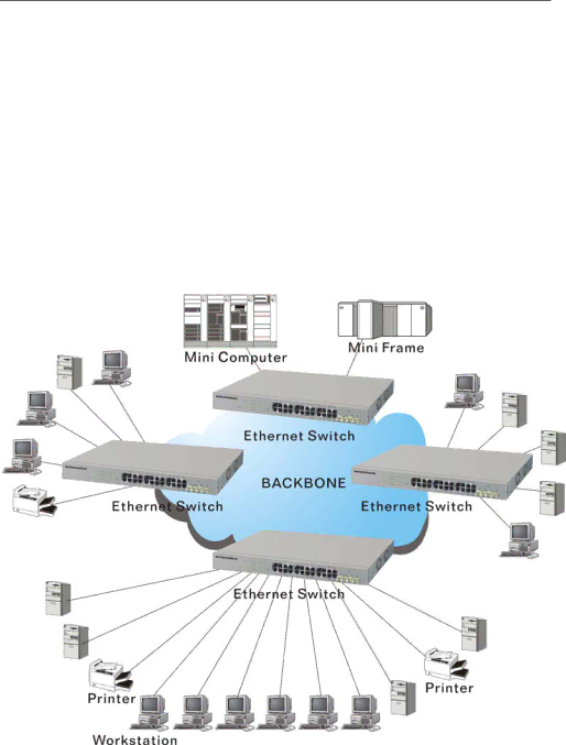
Fig. 3-7

In the figure above, all stations are within the same broadcast domain. For these stations, it is obviously that the traffic is getting congested while adding more stations on it. With the more and more users joining the LAN, broadcast traffic will rapidly decrease the performance of the network. Finally, the network may get down.

39

Image 45
Contents KGS-2404 Page Release Table of Contents 100 Federal Communications Commission FCC Statement 06/28/2007 03/13/2007 02/10/2007About this user’s manual Overview of 24-Port GbE Web Smart Switch Key Features in the DeviceVlan Features ChecklistHardware ManagementPage User Interfaces on the Front Panel Button, LEDs and Plugs View of 24-Port GbE Web Smart SwitchUser Interfaces on the Rear Panel LED IndicatorsSystem LED 10/100/1000Ethernet TP Port 1 to 24 LEDFront View of 1000Base-SX/LX LC, SFP Fiber Transceiver View of the Optional ModulesStarting 24-Port GbE Web Smart Switch Up Hardware and Cable InstallationConnecting the SFP Module to the Chassis Power On TP Port and Cable InstallationCabling Requirements Firmware LoadingCabling Requirements for 1000SX/LX SFP Module Cabling Requirements for TP PortsTypical Network Topology in Deployment 1000Base-X TP, Fiber 100Base-TX TP 100Base-FX FiberNo Vlan Configuration Diagram Case 2b Port-based Vlan See -4 Page Management through Ethernet Port Managing 24-Port GbE Web Smart Switch through Ethernet PortIP Address Assignment Login Screen for Web110 10000000.00000001.00000010.1 Prefix Length No. of IP matched No. of Addressable IP Page 10 Network Connection between Remote Site and Central Site Typical Applications11 Peer-to-peer Network Connection What’s the Ethernet Basic Concept ManagementIEEE802.3 CSMA/CD MAC Snap STP BpduARP SAP Format Media Access Control MACFCS PRE SFDPage How does a MAC work? Bytes DTE Flow Control Page Bits How does a switch work? Collision Domain Page Page Virtual LAN Page Tag Format CFIPage Page VID Link Aggregation 10 Example of Link Aggregation Application Operation of Web-based Management Web Management Home Overview Information of Page Layout Snmp Lacp RstpFunction description System ConfigurationPage Page ON/OFF Port ConfigurationPort Configuration Vlan Mode ConfigurationSelect Vlan Mode VID Vlan Group ConfigurationAdd or Remove Vlan Member Page Aggregation 10 Aggregation/Trunking ConfigurationLacp 11 Lacp Port ConfigurationRstp Rstp Port Configuration Page Page Page Port Mode Port Control Authentication Port Status Radius IP 16 802.1X Configuration 802.1x Parameters Vlan ID Igmp Snooping20 Mirror ports configuration Mirror Configuration21 QoS Configuration QoSQuality of Service ConfigurationQoS Configuration Dscp Setting Dhcp Filter24 Filter Configuration Rate Limit 25 Rate Limit ConfigurationStorm Control 26 Storm Control ConfigurationPage Parameters description Snmp27 Snmp Configuration Statistics Overview Monitoring28 Statistics Overview for all ports Detailed Statistics Page 29 Detailed Statistics for each port 30 Lacp Status Lacp StatusRstp Status 31 Rstp Status Igmp Status 32 Igmp Status Ping Status33 Ping Maintenance 34 Warm Restart Warm RestartFactory Default 36 Software Upgrade Software UpgradeFunction description Configuration File TransferLogout Q&A Resolving No Link ConditionAppendix a Technical Specifications SFP ƒ Network Interfaceƒ MAC Address and Self-learning 8K MAC address ƒ Cable and Maximum Lengthƒ Power Requirement ƒ Diagnostic LEDAmbient Temperature DimensionsManagement Software Specifications From RFC1213-MIB PRIVATE-GESM-SW24L-MIB Definitions = Begin ImportsFrom RFC1155-SMI OBJECT-TYPE