EVGA 650I manual Connecting IDE Hard Disk Drives, Pin ATX 12V Power PWR2

Page 28

Hardware Installation

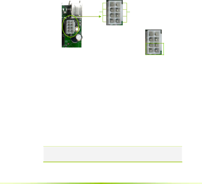
8-pin ATX 12V Power (PWR2)

PWR2, the 8-pin ATX 12V power connection, is used to provide power to the CPU. Align the pins to the connector and press firmly until seated.

Backpanel connector edge.

12V

5 1

GND

84

Connect a four-pin power plug to pins 3, 4, 7, and 8.

51

It is strongly recommended that you use an 8-pin ATX 12V power supply; however, if you have a four-pin power supply, plug the connector to pins 1, 2, 5, and 6 as shown.

Connecting IDE Hard Disk Drives

The IDE connector supports Ultra ATA 133/100/66 IDE hard disk drives.

1.Connect the blue connector (the cable end with a single connector) to the motherboard.

2.Connect the black connector (the cable with the two closely spaced black and gray connectors) to the Ultra ATA master device.

3.Connect the gray connector to a slave device.

If you install two hard disk drives, you must configure the second drive as a slave device by setting its jumper accordingly. Refer to the hard disk documentation for the jumper settings.

Note: If an ATA-66/100 disk drive and a disk drive using any other IDE transfer protocol are attached to the same cable, the maximum transfer rate between the drives may be reduced to that of the slowest drive.

17

Image 28
Contents Page User Guide Table of Contents Unpacking and Parts Descriptions Configuring the Bios Page Page Vii Before You Begin… Parts not in the KitIntentions of the Kit Page Features Ultimate OverclockingHigh-speed Memory Comprehensive Overclocking ToolsMultiple Disk Setup True x16 PCI Express SupportDualDDR2 Memory Architecture Nvidia MediaShield StorageBootable Multidisk Array RAID MorphingNetworking with Nvidia nForce Nvidia Native Gigabit EthernetUSB Motherboard Specifications Page Unpacking EquipmentSata Signal Cable Qty Four Nvidia nForce 650i Ultra MotherboardNvidia nForce 650i Ultra Motherboard Layout Chassis Backpanel Connectors Hardware Installation Safety InstructionsInstalling the CPU Preparing the MotherboardInstalling the CPU Fan Installing Memory DIMMsInstalling the I/O Shield Installing the MotherboardSecuring the Motherboard into the Chassis Connecting Cables Setting Switches ¾ COM ‰ FDD ‰ IDEPower Connections Pin ATX Power PWR1Connecting IDE Hard Disk Drives Pin ATX 12V Power PWR2Connecting Serial ATA Cables Connecting Internal Headers Front Panel HeaderFront Panel Header Pins USB 2.0 Header Pins USB HeadersFront Audio Connector AudioFDD Connector Fan ConnectionsExpansion Slots PCI SlotsJumper Settings Clear Cmos Jumper ClrcmosPCI Express x1 Slots PCI Express x16 SlotConfiguring the Bios Enter Bios Setup Main Menu‰ Standard Cmos Features ‰ Advanced Bios Features‰ Advanced Chipset Features ‰ Power Management Setup‰ Load Defaults ‰ Set Password‰ Save & Exit Setup ‰ Exit Without SavingStandard Cmos Features Menu Standard Cmos Features MenuDate and Time IDE Channel and Sata Channel‰ None ‰ Auto‰ Manual ¾ Large‰ All Errors ‰ No ErrorsDrive a Halt OnMemory ‰ All, But Diskette‰ All, But Disk/Key ‰ Extended MemoryAdvanced Bios Features CdromHard Disk Boot Priority Network Boot PriorityRemovable Device Priority CPU Internal CacheQuick Power On Self Test First/Second/Third Boot DeviceBoot Other Device Boot Up NumLock StatusApic Mode Security OptionMPS Version Control For OS Full Screen Logo ShowAdvanced Chipset Features Advanced Chipset FeaturesSystem Clocks CPU Spread SpectrumFrequency Settings HT Multiplier Spread SpectrumFSB & Memory Config FSB Memory Clock Mode Auto‰ FSB and Memory Clock Mode ¾ Linked¾ Unlinked ‰ FSB QDR, MHz‰ MEM DDR, MHz ‰ Memory Timing Setting¾ Optimal ¾ Expert ‰ Limit Cpuid MaxVal CPU Configuration‰ CPU Thermal Control ‰ Execute Disable Bit System Voltages‰ C1E Enhanced Halt State ‰ Virtualization Technology‰ Memory ‰ nForce SPPNvmem Memory Test Load Timing/Voltage SetSystem Bios Cacheable Save Timing/Voltage SetHpet Function Nvidia GPU ExIntegrated Peripherals Menu Integrated Peripherals MenuIDE Function Setup ‰ IDE DMA transfer access‰ Primary Master/Slave PIO ‰ Primary Master/Slave UdmaRAID Config USB Config‰ RAID Enable ‰ Sata x Primary/SecondaryMAC Config IDE HDD Block ModeHD Audio Onboard FDC ControllerAcpi Function Power Management Setup MenuAcpi Suspend Type Power On by Alarm Power on Function‰ Password Soft-Off by Pbnt‰ Hot Key Power On PnP/PCI Configuration Menu‰ Mouse Left Init Display First Reset Configuration DataResources Controlled By PCI/VGA Palette Snoop IRQ ResourcesMaximum Payload Size System Monitor Menu System Monitor MenuDynamic Fan Control Press Enter to display the Dynamic Fan Control menuHardware Installation