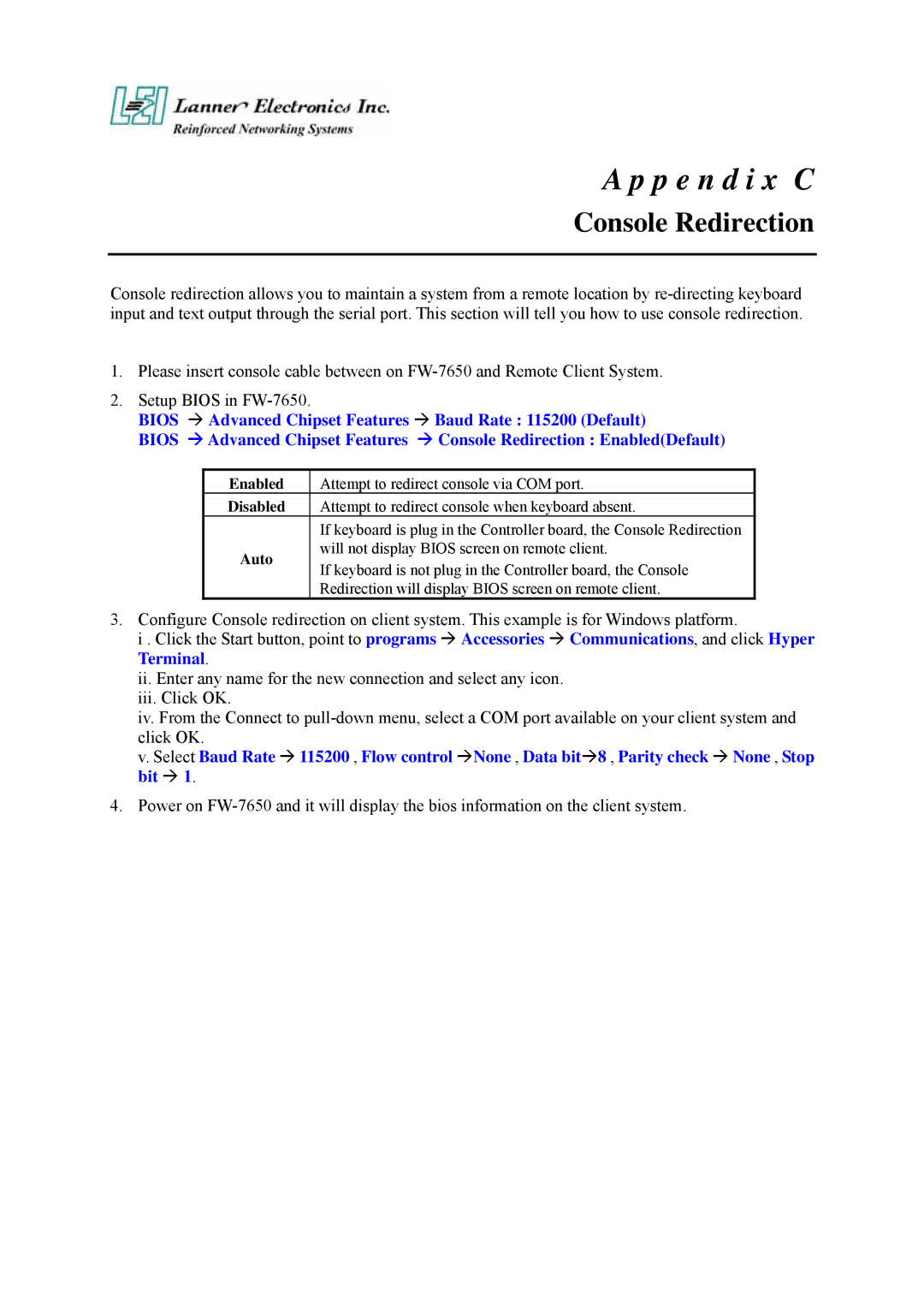
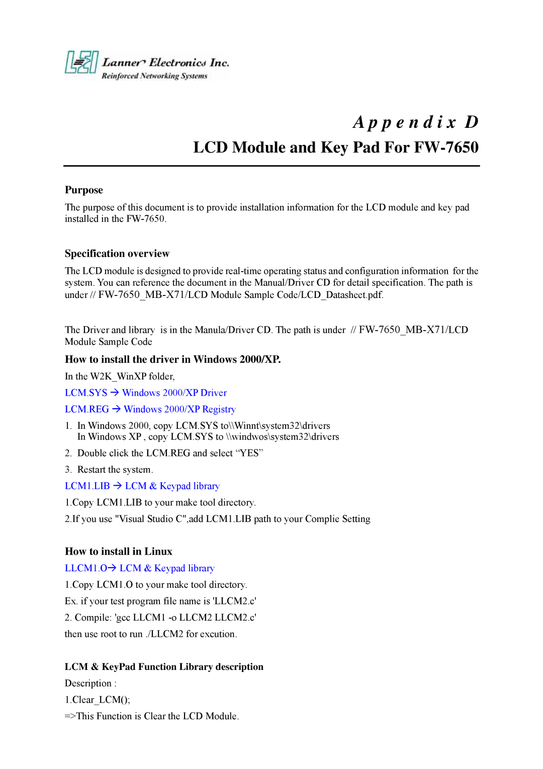
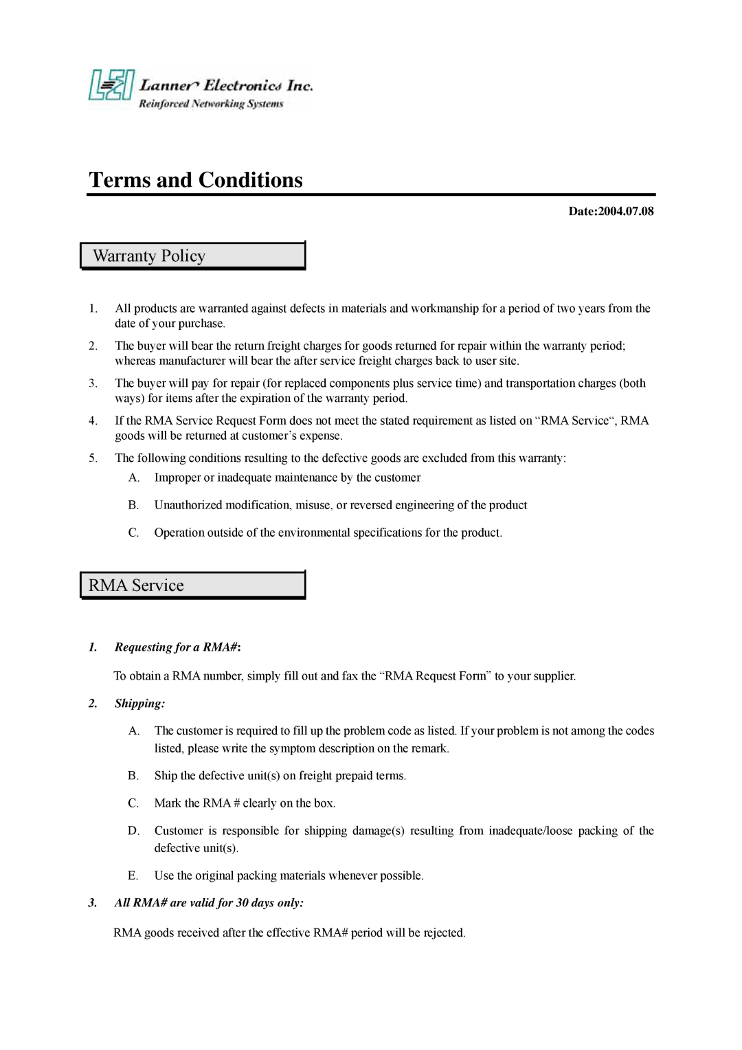
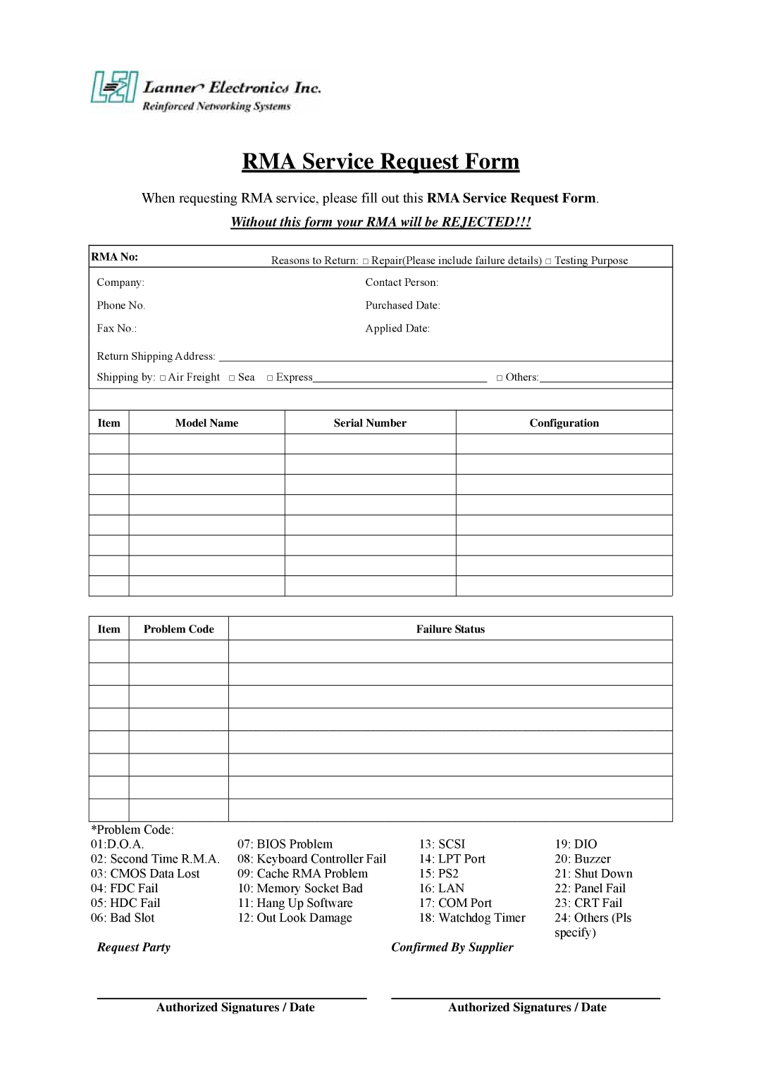
Lanner electronic FW-7650 manual Watchdog Timer, Detail Register, Bit, and Pin Descriptions

Page 50

Appendix B

Watchdog Timer

Introduction

Most systems need to be self-reliant. It's not usually possible to wait for someone to reboot them if there are some component wrong. Some system designs, such as space probes, are simply not accessible to human operators. If the system ever hangs, such systems are permanently disabled. In other cases, the speed with which a human operator might reset the system would be too slow to meet the uptime requirements of the product.

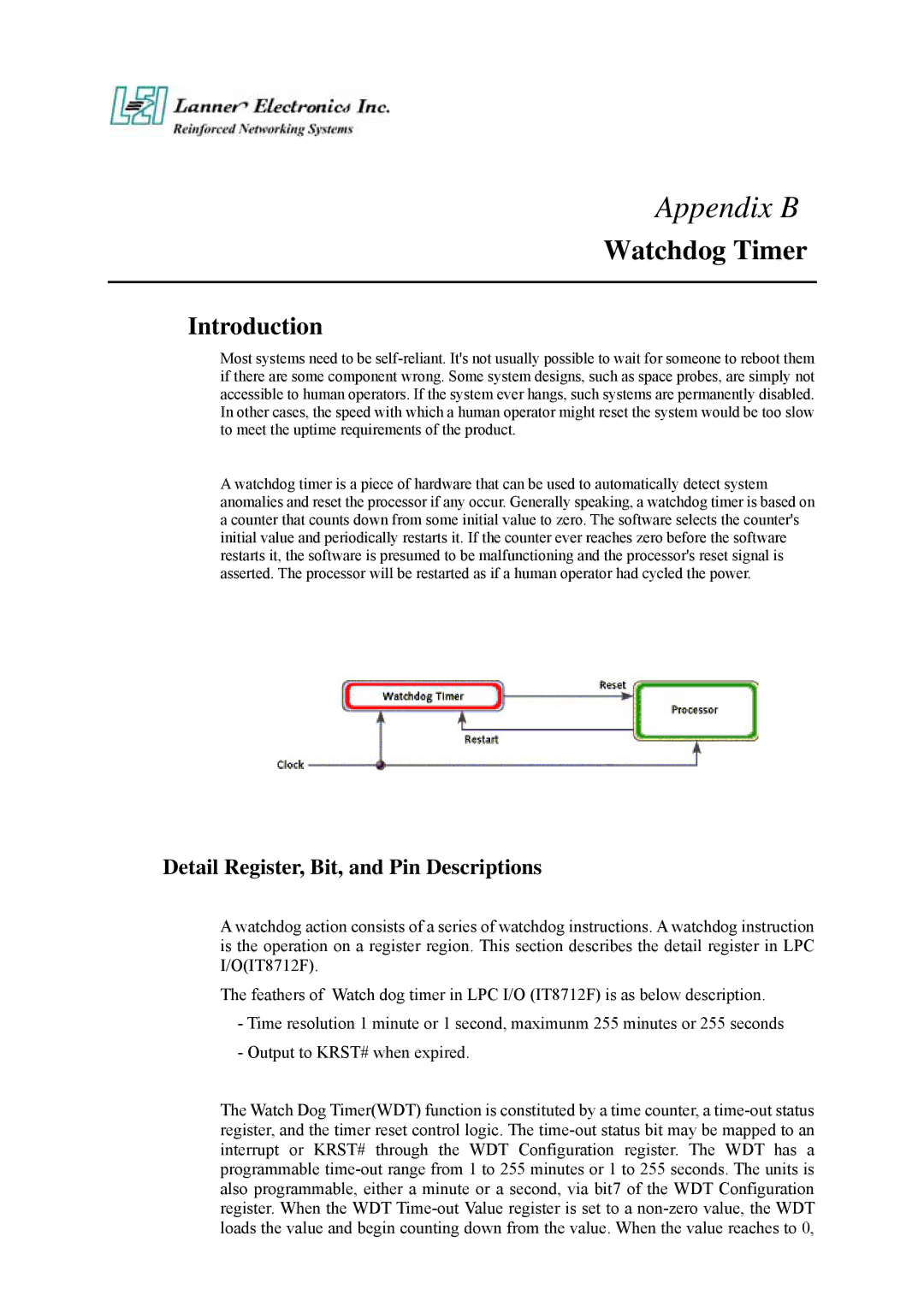
A watchdog timer is a piece of hardware that can be used to automatically detect system anomalies and reset the processor if any occur. Generally speaking, a watchdog timer is based on a counter that counts down from some initial value to zero. The software selects the counter's initial value and periodically restarts it. If the counter ever reaches zero before the software restarts it, the software is presumed to be malfunctioning and the processor's reset signal is asserted. The processor will be restarted as if a human operator had cycled the power.

Detail Register, Bit, and Pin Descriptions

A watchdog action consists of a series of watchdog instructions. A watchdog instruction is the operation on a register region. This section describes the detail register in LPC I/O(IT8712F).

The feathers of Watch dog timer in LPC I/O (IT8712F) is as below description.

-Time resolution 1 minute or 1 second, maximunm 255 minutes or 255 seconds

-Output to KRST# when expired.

The Watch Dog Timer(WDT) function is constituted by a time counter, a time-out status register, and the timer reset control logic. The time-out status bit may be mapped to an interrupt or KRST# through the WDT Configuration register. The WDT has a programmable time-out range from 1 to 255 minutes or 1 to 255 seconds. The units is also programmable, either a minute or a second, via bit7 of the WDT Configuration register. When the WDT Time-out Value register is set to a non-zero value, the WDT loads the value and begin counting down from the value. When the value reaches to 0,

Image 50
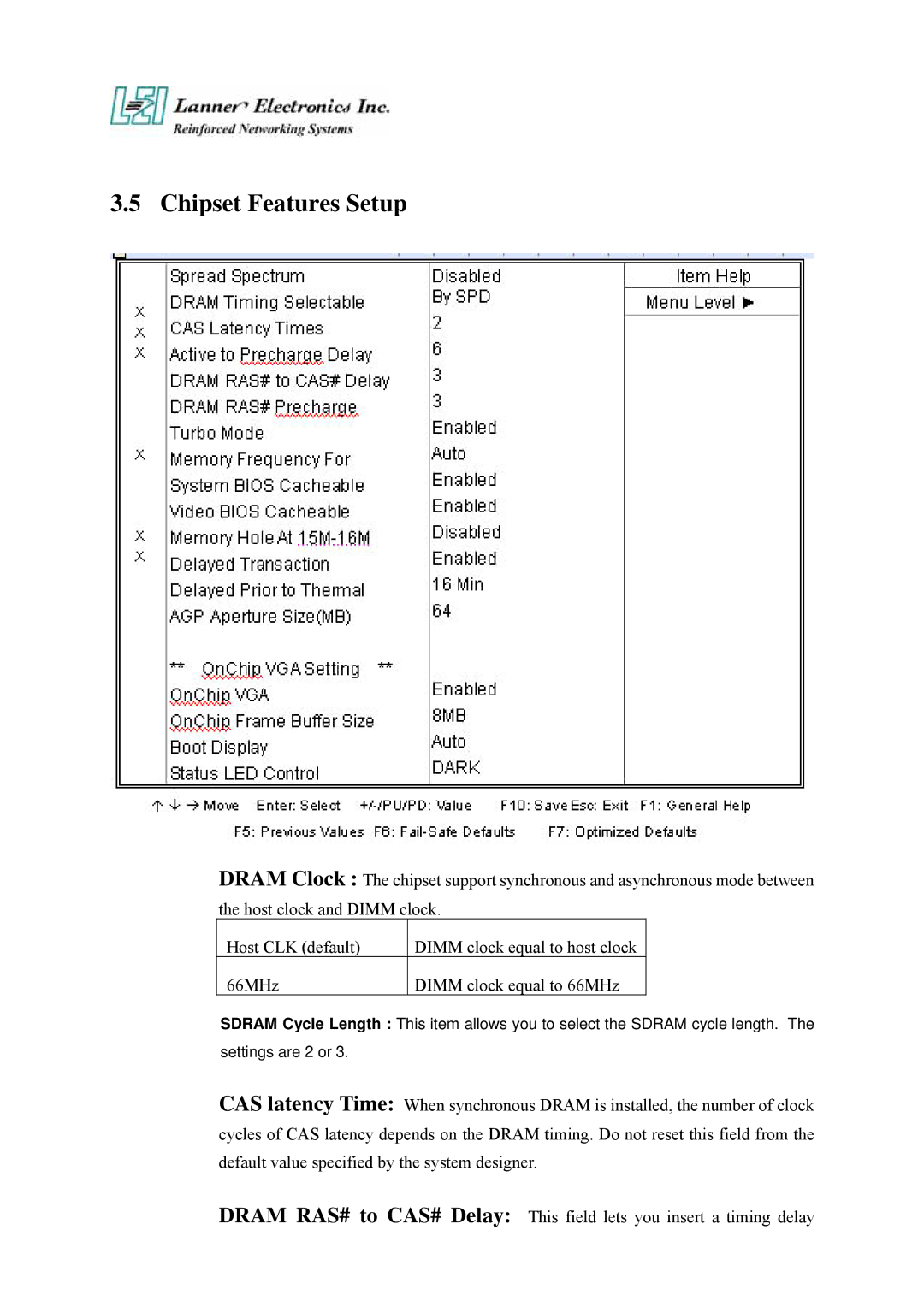
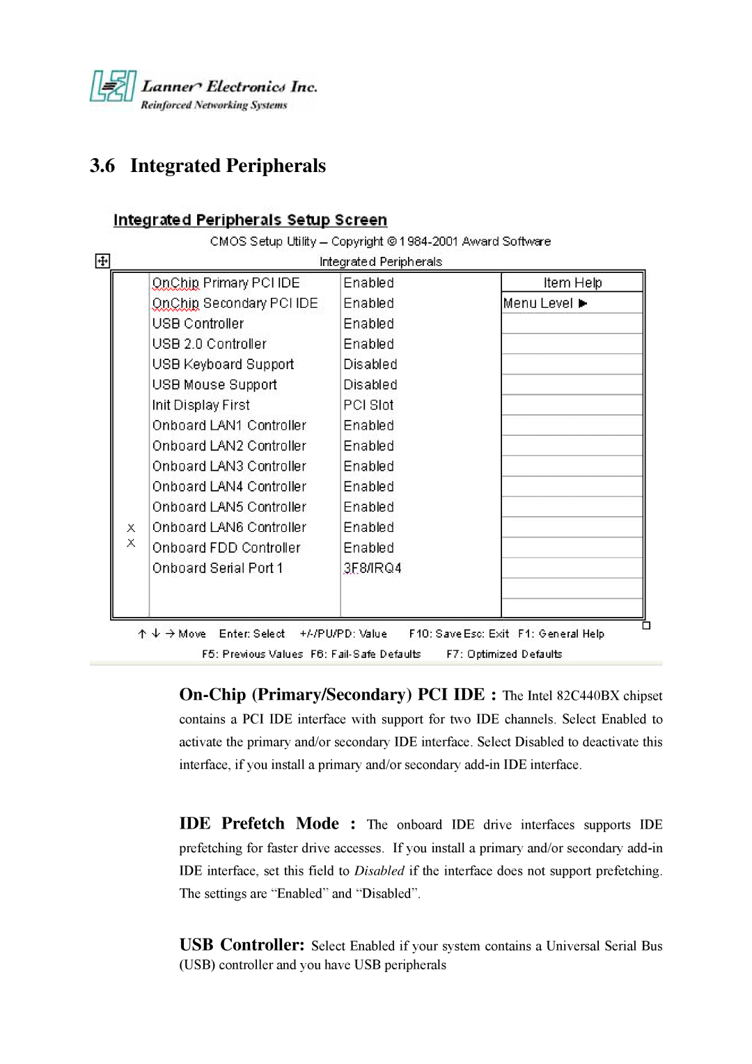
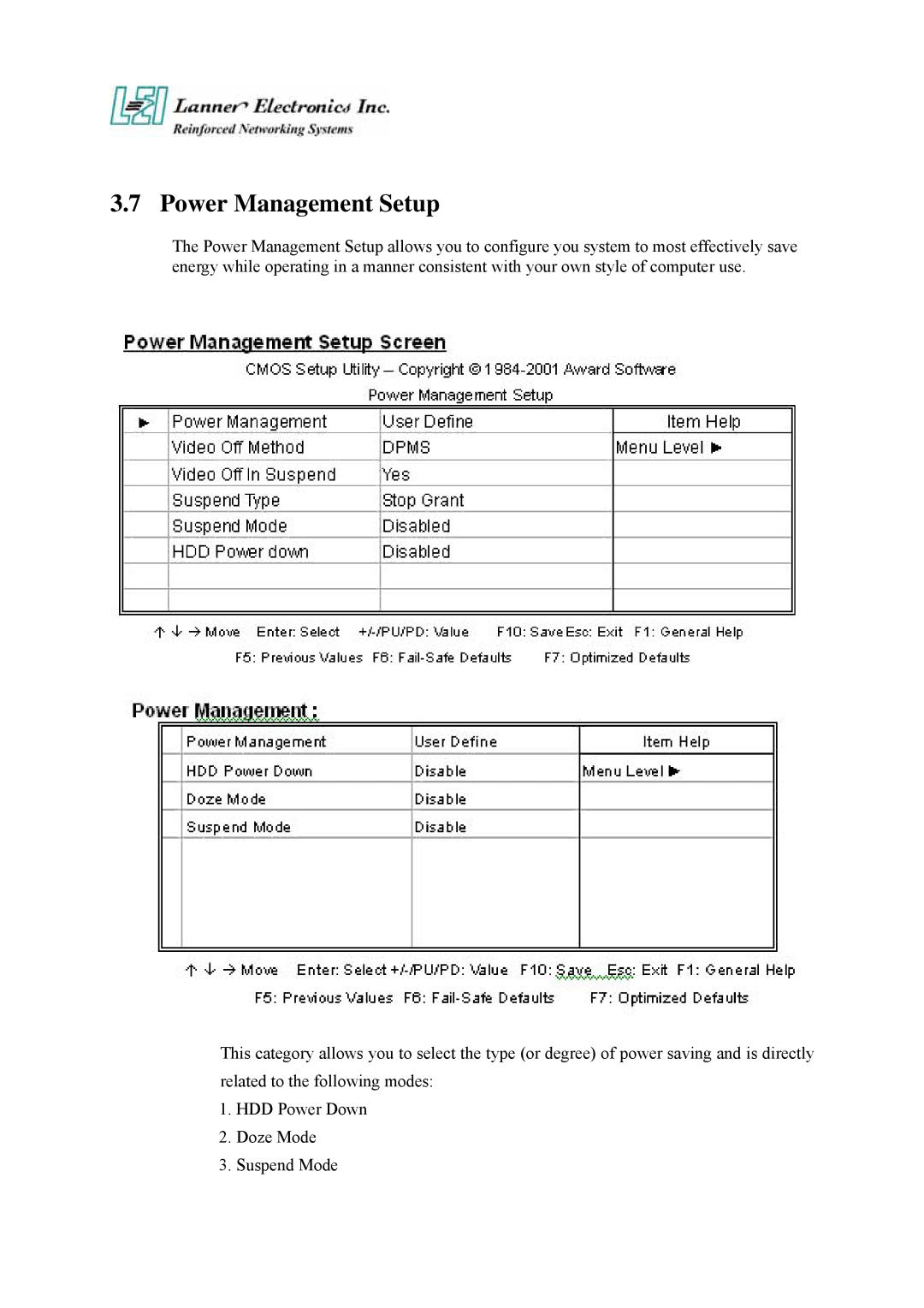
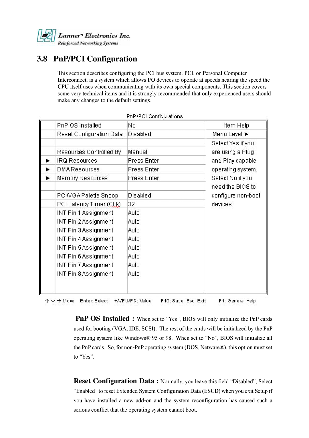
Contents FW-7650 Series User’s ManualTrademark Acknowledgments Radio Frequency Emissions NoticeCopyright and Disclaimers Safety Instructions Getting Technical Assistance About this ManualTable of Contents Warranty Policy RMA Service Power SupplyWatchdog Timer P e n d i x C P e n d i x D LCD Module and Key Pad For FW-7650Introduction FeaturesGetting Started Technical Specifications Packing Contents MB-X71 System Board Board LayoutJumper Settings and I/O Connector Jumper FunctionSFC1Master/Slave Select Connector Pin AssignmentsDescription Normal Default Clear Cmos CMOS1Clear Cmos DataCOMA1 RS-232 Serial Port #1 Connector D-Sub LANA3~6 Type 1 RJ-45LCMA1:LCM Connector VGAB1 External VGA Connector 12 Pin Header IDEA1 IDE Interface Connector 44Pin 2.0mm Pitch HeaderPLRS1Power LED,HD LED,Reset,Speaker Connector11 Pin 2.54mm FDCA1 Floppy Interface Connector 34 Pin HeaderCF1Compact Flash Connector LEDE1:2x22 Pin IDEB1 IDE Interface Connector 40Pin 2.54mm Pitch Header PCIB1124 Pin Mini PCI Socket PCIB1124 Pin Mini PCI Socket last Face Panel LED Status and Behavior FW-7650 19 1U Rackmount Firewall MechanismsFace Panel Rear View FW-7650 Rear ViewFW-7650 Hardware Installation Guide Inside of FW-7650 CPU InstallationSystem Memory How to Remove the Hard Disk Bay Installing Compact Flash Card Installing the Mini-PCI CardStarting Setup Award Bios SetupBios Setup Using SetupGetting Help Cmos Setup UtilityNavigating through the menu bar General Help F6 Fail-Safe DefaultsF7 Optimized Defaults Previous ValuesStandard Cmos Features IDE Adapters Bios Features Setup CapacityPage C8000-CBFFF Shadow to DC000-DFFFF Shadow The default Chipset Features Setup Page Integrated Peripherals On-Chip Primary/Secondary PCI IDE The Intel 82C440BX chipsetPage Power Management Setup Always turn on PnP/PCI Configuration Page Page Page PC Health Status Save and Exit Setup Load Optimized DefaultsSupervisor/User Password Setting Exit Without Saving Quit without saving Y/N? YOutput Specifications Power SupplyPower Supply Specification FeatureWatchdog Timer Detail Register, Bit, and Pin DescriptionsWatch Dog Timer Control Register Index =71h, Default=00h P e n d i x C Console RedirectionLCD Module and Key Pad For FW-7650 LCM & KeyPad Function Library descriptionPage Warranty Policy Terms and ConditionsRMA Service Request Form Without this form your RMA will be RejectedPEXNSD01-040709 Version 1.0 Printed and published in Taiwan

FW-7650 specifications

The Lanner FW-7650 is a robust network appliance specifically designed to meet the demands of modern firewall and routing applications. This versatile device incorporates advanced technologies and features that make it suitable for a variety of network environments, including data centers, enterprises, and service providers.

One of the primary characteristics of the FW-7650 is its high-performance hardware. The appliance is powered by Intel's latest processors, which deliver exceptional processing power and efficiency. Leveraging multi-core architectures, the FW-7650 can handle intensive workloads, making it well-suited for tasks such as deep packet inspection and intrusion detection.

The FW-7650 supports various network interfaces, including multiple Gigabit Ethernet ports, enabling high-speed connectivity and redundancy. This flexibility allows administrators to configure the device according to specific network requirements, whether that be in a high-traffic environment or a more modest setup. Additionally, the appliance offers support for additional expansion modules, allowing further customization and scalability.

Equipped with advanced security features, the Lanner FW-7650 is designed to protect sensitive data against emerging threats. The appliance supports stateful firewall and application firewall capabilities, allowing it to effectively monitor and control network traffic. Furthermore, it includes features such as VPN support, intrusion prevention systems (IPS), and content filtering, ensuring a comprehensive defense against cyber threats.

In terms of management, the FW-7650 provides a user-friendly interface for easier configuration and monitoring. The appliance is compatible with open-source firewall software and supports industry-standard protocols, ensuring that it can be integrated seamlessly into existing network infrastructures. Remote management capabilities further enhance usability, allowing network administrators to oversee performance metrics and security logs from anywhere.

Energy efficiency is another highlight of the FW-7650. Designed with environmental considerations in mind, the appliance incorporates power-saving technologies that reduce operational costs while maintaining performance. This makes it an ideal choice for organizations seeking to minimize their ecological footprint without compromising on network security.

In conclusion, the Lanner FW-7650 is a powerful and flexible network appliance that is well-equipped to address today's cybersecurity challenges. With its high-performance capabilities, advanced security features, and user-friendly management options, it stands out as a reliable solution for businesses looking to enhance their network defenses. Whether deployed in a corporate environment or as part of a service provider’s infrastructure, the FW-7650 is engineered for superior performance and adaptability.