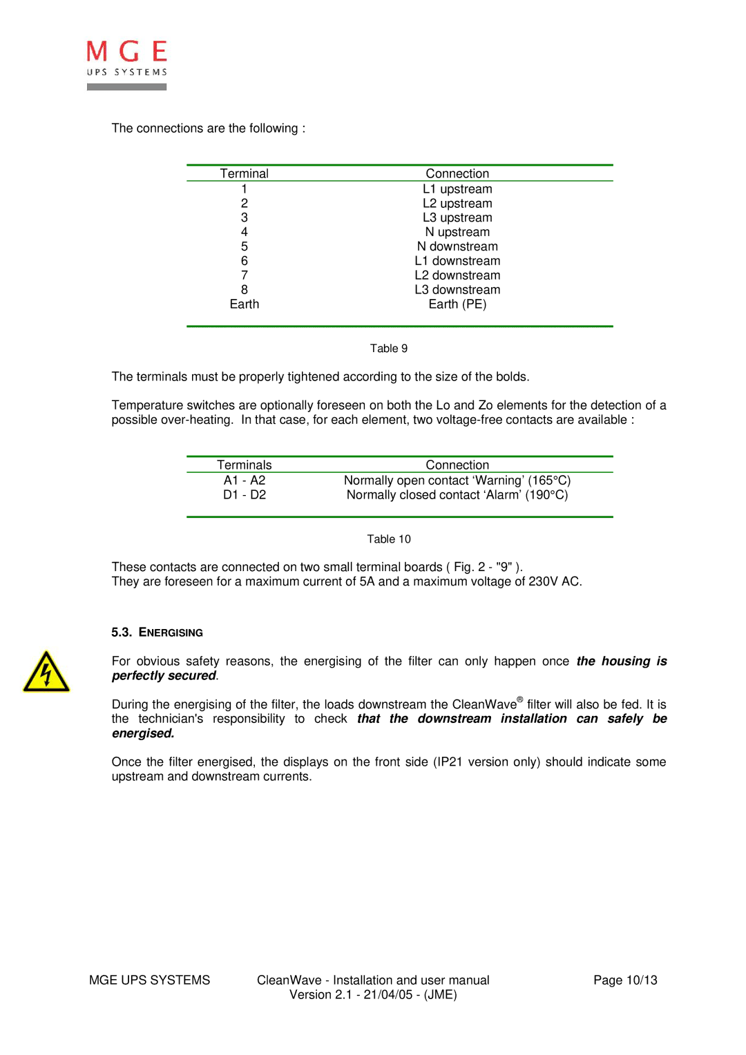
5. INSTALLATION AND STARTING
5.1.HANDLING
The filters are delivered on a wooden tray and can easily be moved with the help of a forklift. They can also be handled with the help of the lifting rings.
5.2.ELECTRICAL CONNECTIONS
The electrical connections must be done with no voltage by a qualified electrician.
| D1 Breaker | ‘Upstream’ |
|
|
|
| ‘Downstream’ |
| |||||
| terminals |
|
|
|
|
| terminals |
| |||||
|
|
|
|
|
|
|
|
|
| ||||
|
|
|
|
|
|
| 1 |
| 6 |
|
|
|
|
To |
|
|
| L1 |
|
| 2 | CleanWave→ | 7 |
|
| L1 | To |
|
|
|
|
|
|
|
|
| |||||
|
|
| L2 |
|
|
|
| L2 | distorting | ||||
mains |
|
|
|
|
| 3 |
| 8 |
|
| |||
|
|
|
|
|
|
|
|
|
| load | |||
|
|
|
| L3 |
|
| 4 |
| 5 |
|
| L3 |
|
|
|
|
|
|
|
|
|
|
|
|
| ||
|
|
|
| N |
|
|
|
|
|
|
| N |
|
|
|
|
|
|
|
|
|
|
|
|
|
|
|
PE
Earth
Fig. 7
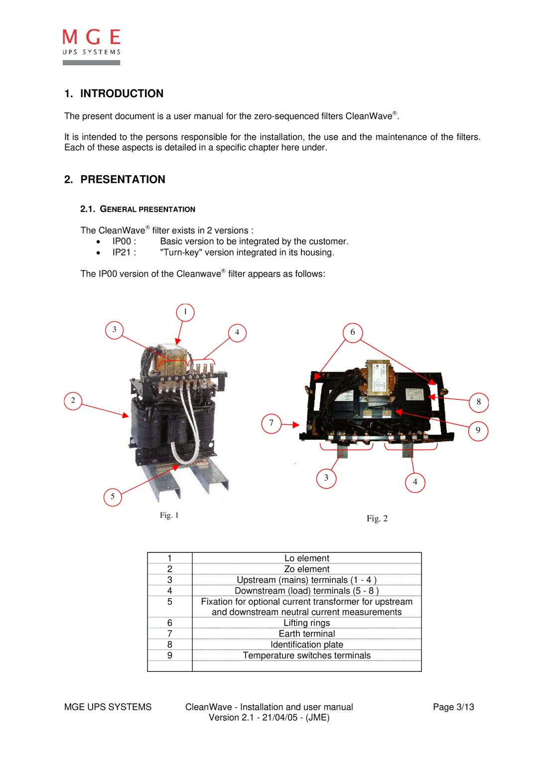
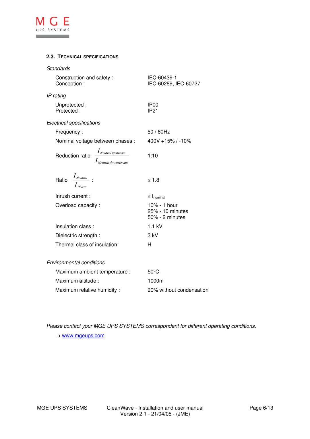
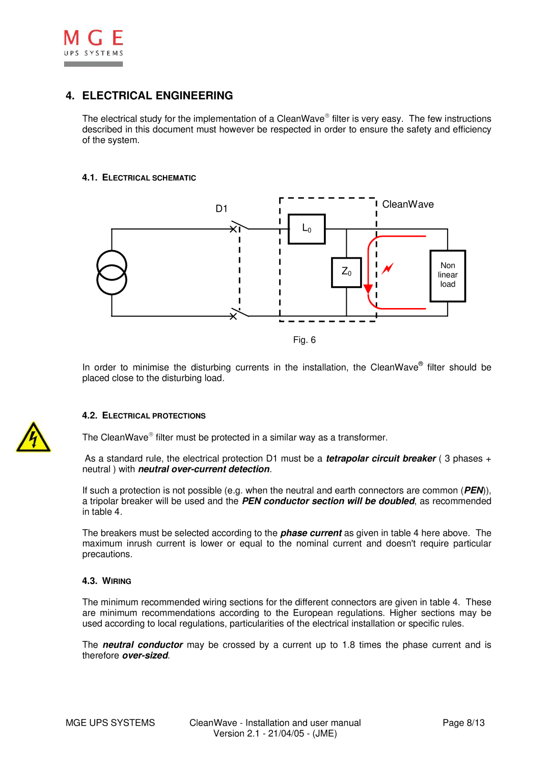
The power connections (see fig. 1 et 2) are done on the upstream (3) and downstream (4) terminals.
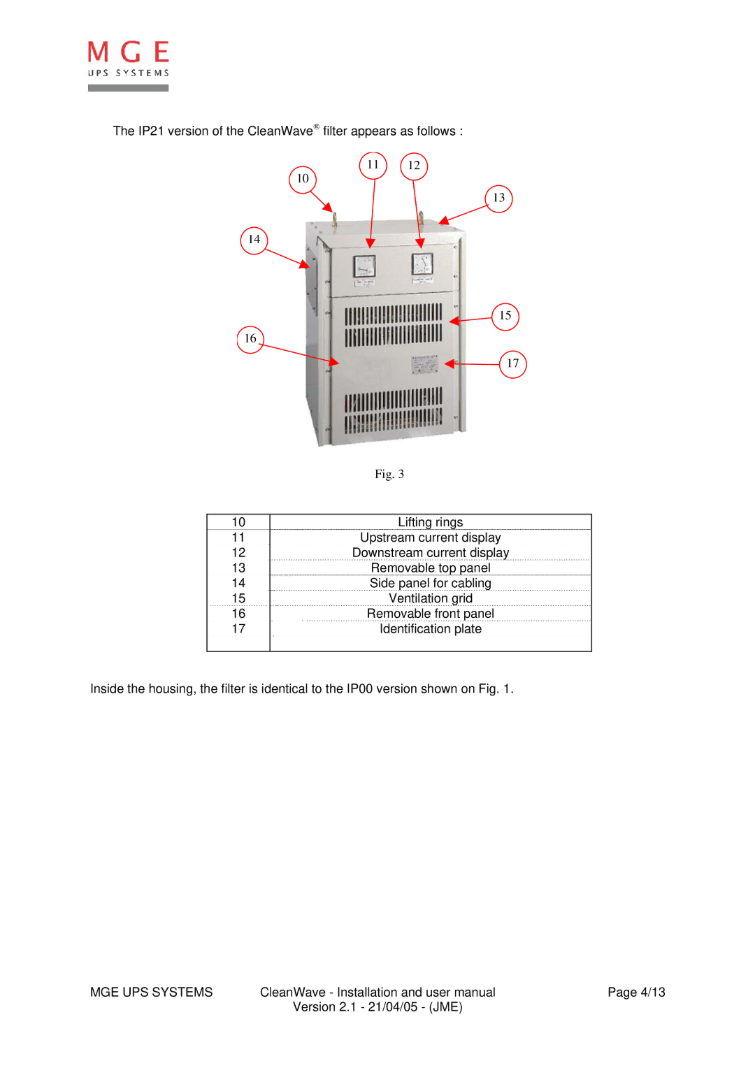
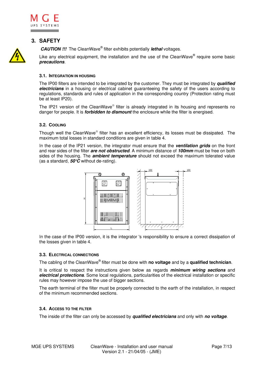
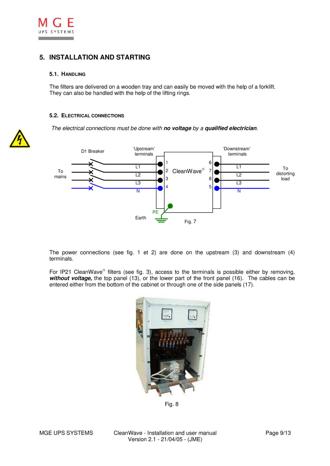
For IP21 CleanWave→ filters (see fig. 3), access to the terminals is possible either by removing, without voltage, the top panel (13), or the lower part of the front panel (16). The cables can be entered either from the bottom of the cabinet or through one of the side panels (17).
Fig. 8
MGE UPS SYSTEMS | CleanWave - Installation and user manual | Page 9/13 |
| Version 2.1 - 21/04/05 - (JME) |
|
