Acer R3700 manual Remove the Battery

Page 44

Remove the Battery.

1.Place the motherboard on a clean, static-free work surface.

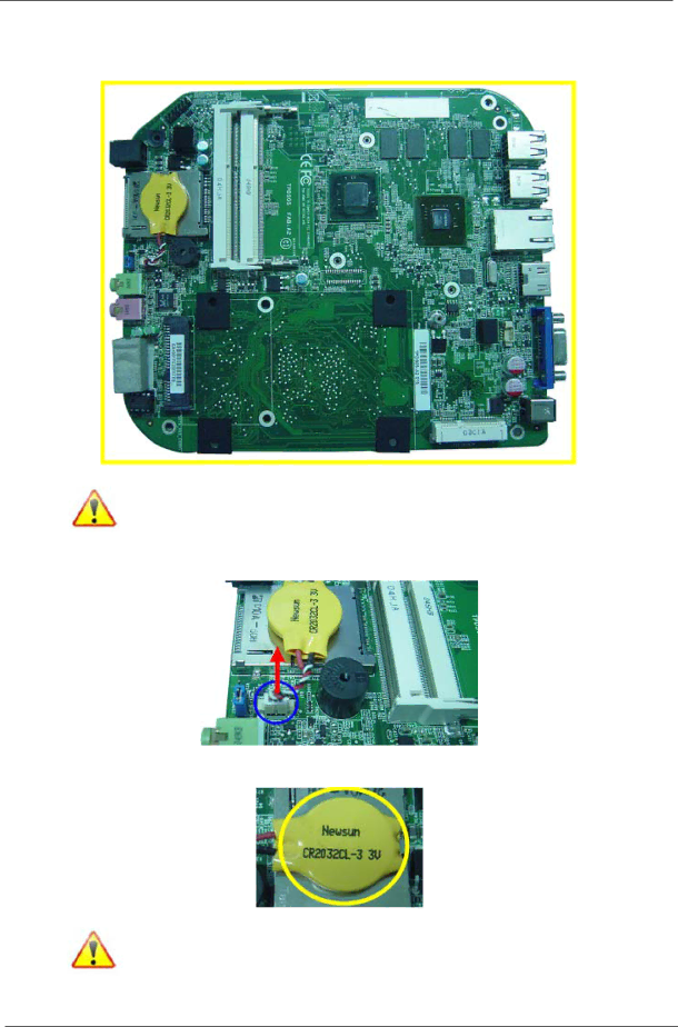
Note:Circuit boards >10 cm² has been highlighted with the yellow rectangle as above image shows. Please detach the Circuit boards and follow local regulations for disposal.

2.Disconnector the cable from the motherboard.

3.Remove the battery.

Note:RTC battery has been highlighted with the yellow circle as above image shows.Please detach the RTC battery and follow local regulations for disposal.

38

Chapter 3

Image 44
Contents Acer Aspire R3700 Service Guide Revision History Copyright Disclaimer Conventions Service Guide Coverage Table of Contents Features ChapterOn-Board Graphic solution Hard diskOptical disk Serial ATA controllerAdapter All On-Board ConnectorsSystem Bios Block Diagram System Components Front PanelRear Panel Hardware Specifications and Configurations Bios Hotkey ListProcessor Main Board Major ChipsAudio Interface Memory CombinationsSystem Memory Power Management Sata InterfaceUSB Port Environmental RequirementsPower Management FunctionACPI support function Device Standby ModeGlobal Standby Mode Suspend ModeCmos Setup Utility System UtilitiesEntering Cmos setup Navigating Through the Setup UtilitySetup Utility Menus Parameter DescriptionProduct Information Standard Cmos Features Parameter Description OptionAdvanced Bios Feature EnabledAdvanced Chipset Features Integrated Peripherals Power Management Setup PC Health Status Frequency/Voltage Control Bios Security Features Load Default Settings Save and Exit Setup Exit Without Saving System Disassembly Disassembly RequirementsPre-disassembly Procedure Removing the Side Panel Removing the CPU Fan Removing the CPU Cooler Removing the Memory Modules Removing the Front D/B Removing the Wireless LAN Card Removing the S/PDIF Cover Removing the Main Board Removing the Hard Disk Drive Remove the Battery System Troubleshooting System Internal Inspection Power System CheckSystem External Inspection Beep Codes Checkpoints Viewing Bios checkpointsBootblock Initialization Code Checkpoints Bootblock Recovery Code Checkpoints Checkpoint DescriptionBios Recovery Choose OK and press Enter keyJumper and Connector Information PlacementJumper Setting Setting JumperSystem Board Pin Definition Jumper/Header Name Function DefinitionFRONTUSB1 5USBREARPW Front USB2 2USB0FBJ 6GND 7GND 8GND 95VCONN Gndgnd SD-9SDDAT2 XD-18XDD7 FRU Field Replaceable Unit List Aspire R3700 Exploded Diagram NameCategory Description Part Number Exploded Diagram Item Aspire R3700 FRU ListWD3200BEVT-22A23T0,ML320S,WD Sata Chapter Category Description Part Number Exploded Chapter Category Description Part Number Exploded Diagram Item