Acer 4010 manual Disassembling the LCD Module

Page 73

Disassembling the LCD Module

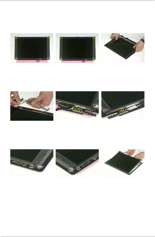
1.Remove the four screw caps as shown.

2.Remove the four screws holding the LCD bezel.

3.Then detach the LCD bezel from the LCD module.

4.Disconnect the inverter board then remove it.

5.Remove the three screws holding the right hinge.

6.Then remove the three screws that secure the left hinge.

7.Remove one screw that secure the LCD bracket.

8.Remove another screw holding the LCD bracket on the other side.

9.Then detach the LCD panel from the LCD cover carefully.

.

10.Remove the two screws holding the right bracket.

11.Then remove the right bracket.

12.Remove another two screws that tighten the left bracket.

Chapter 3

65

Image 73
Contents Acer TravelMate 4010 Series Revision History Date Chapter UpdatesDisclaimer CopyrightScreen Messages ConventionsPreface Page Table of Contents FRU Field Replaceable Unit List TroubleshootingFeatures System SpecificationsExpansion Block DiagramSystem Top View Board LayoutCRT Bottom ViewPcmcia No IR for TM4010 Front Open View TravelMate tourIcon Description Power button Turns the computer on and off Chapter Front Closed View Left View Right Panel Rear Panel Bottom Panel Icon Function Description IndicatorsDesired Access Num Lock On Num Lock Off Using the KeyboardLock Keys and embedded Numeric Keypad Lock Key DescriptionKey Icon Description Windows KeysHot Key Icon Function Description Hot KeysPage Special Key Euro symbolLaunch Keys Launch Key Default applicationDescription Default application Touchpad Basics TouchpadFunction Left Button Right Button Scroll Button Tap Chapter Specification Hardware Specifications and ConfigurationsProcessor Second Level CacheLAN Interface Memory CombinationsIR InterfaceNo IR interface for TM2320/4010 Series Modem InterfaceWireless Module 802.11b/g optional device Bluetooth InterfaceHard Disk Drive Interface DVD-Dual Interface Combo Drive Interface2MB Audio Jack Audio InterfaceVideo Interface AGP8XUSB Port Video MemoryIeee 1394 Port Pcmcia PortKeyboard BatteryQDI QD141XLH12 QDI LCD 15 inchLCD Inverter LCD 15 inch and 15.4 inchAC Adaptor SamsungSystem Power Management Chapter System Utilities Bios Setup UtilityNavigating the Bios Utility Parameter Description InformationMain Advanced Security Boot ExitParameter Description Format/Option Parameter Description Options AdvancedIRQ7/IRQ5 DMA3/DMA1Chapter Security Boot ExitParameter Description Option Clear or SetRemoving a Password Page CD-ROM/DVD Drive BootExit Info Main Advanced Security BootCear Bios Password SOP Bios Flash UtilityCear HDD Password SOP Check HDD Master ID number Chapter Machine Disassembly and Replacement Screw Type Location Quantity General InformationChapter Disassembly Procedure Flowchart Screw List Removing the Battery Pack Removing the HDD Module Chapter Removing the ODD Module Chapter Disassembling the Main Unit Disassembling the Lower Case Assembly Page Chapter Disassembling the LCD Module Chapter Disassembling the External Modules Chapter Symptoms Verified Go To TroubleshootingExternal Diskette Drive Check System Check ProceduresExternal CD-ROM Drive Check Keyboard or Auxiliary Input Device CheckPower System Check Touchpad check Check the Battery PackPower-On Self-Test Post Error Message Error Message List Index of Error MessagesError Messages FRU/Action in Sequence No beep Error Messages FRU/Action in Sequence Code Beeps Post Routine Description Phoenix Bios Beep CodesChapter Code Beeps Post Routine Description Chapter LCD-Related Symptoms Index of Symptom-to-FRU Error MessageIndicator-Related Symptoms Power-Related SymptomsMemory-Related Symptoms PCMCIA-Related SymptomsSpeaker-Related Symptoms Power Management-Related SymptomsKeyboard/Touchpad-Related Symptoms Peripheral-Related SymptomsModem/LAN-Related Symptoms Intermittent Problems Dimm Undetermined ProblemsChapter FRU Field Replaceable Unit List Exploded Diagram TravelMate Power Cord PRC 3 PIN Power Cord US 3 PINPower Cord EU 3 PIN Power Cord UK 3 PINHeatsink Cover Wireless LAN AntennaHDD Cover 1 Dummy CoverDVD/CDRW Combo Drive 24X QSI SBW DVD-ROM Drive 8X QSI SDR-083DVD/CDRW Combo Drive 24X KME Uida DVD Dual Drive QSI SDW-042Darfon UK LCD Module 14.1 IN. XGA QDI LCD Module 14.1 IN. XGA AU B141XG05LCD Module 14.1 IN. XGA CMO N141XB LCD Module 15 IN. XGA AU B150XG01LCD Cable 15 IN. XGA LCD Cable 14.1 IN. XGALCD Cable 15.4 IN. Wxga LCD Bracket W/HINGE 14 IN. LSpeaker SET 512MB Nanya SO-DIMM DDR333 512MBThermal Module VGA Heatsink W/PADIndex Index Index