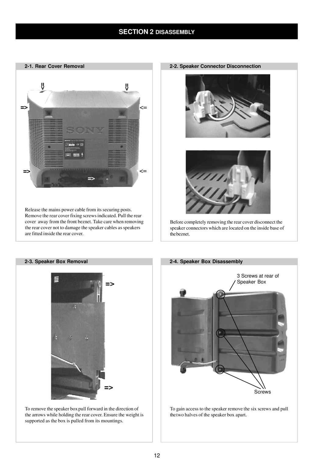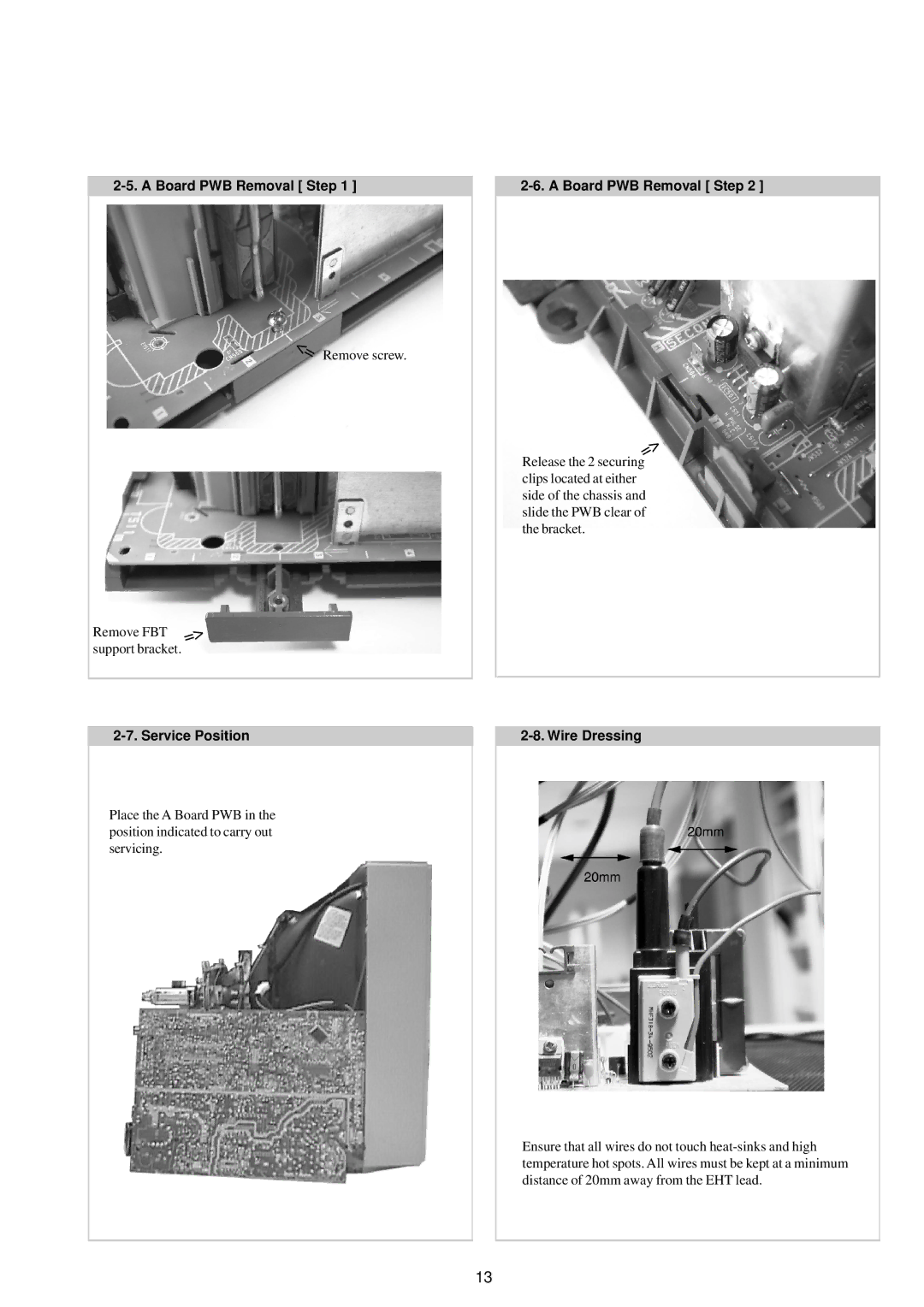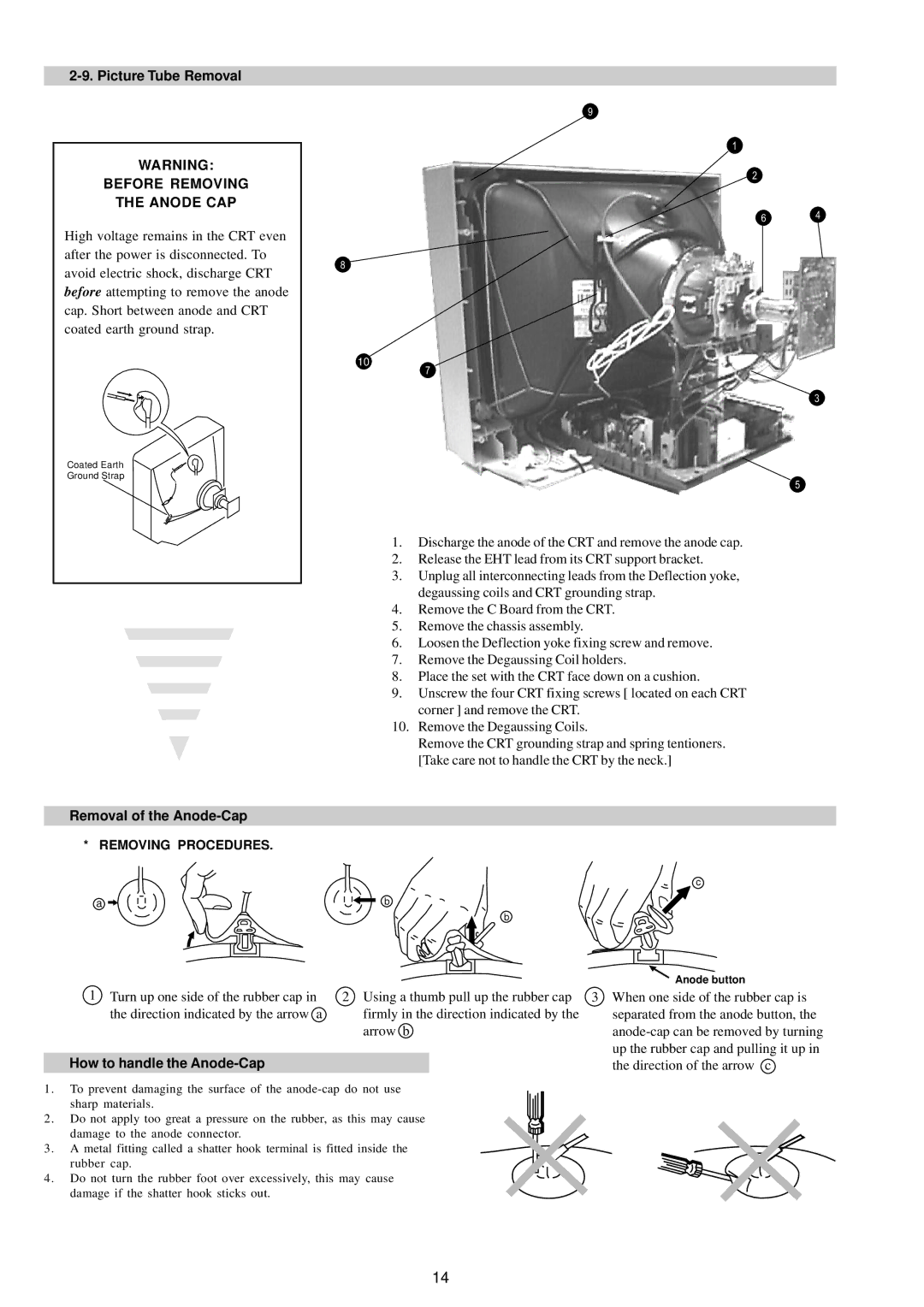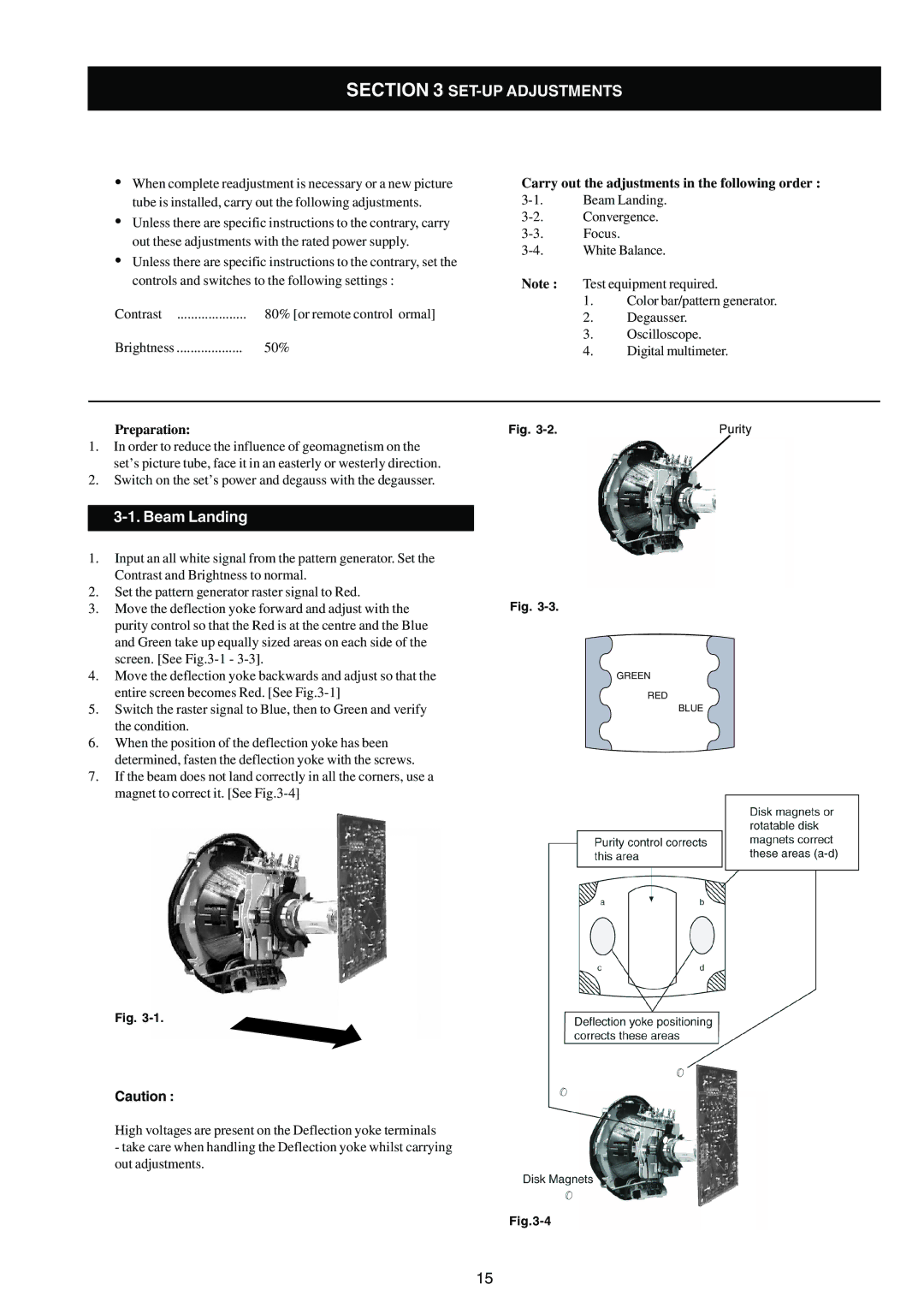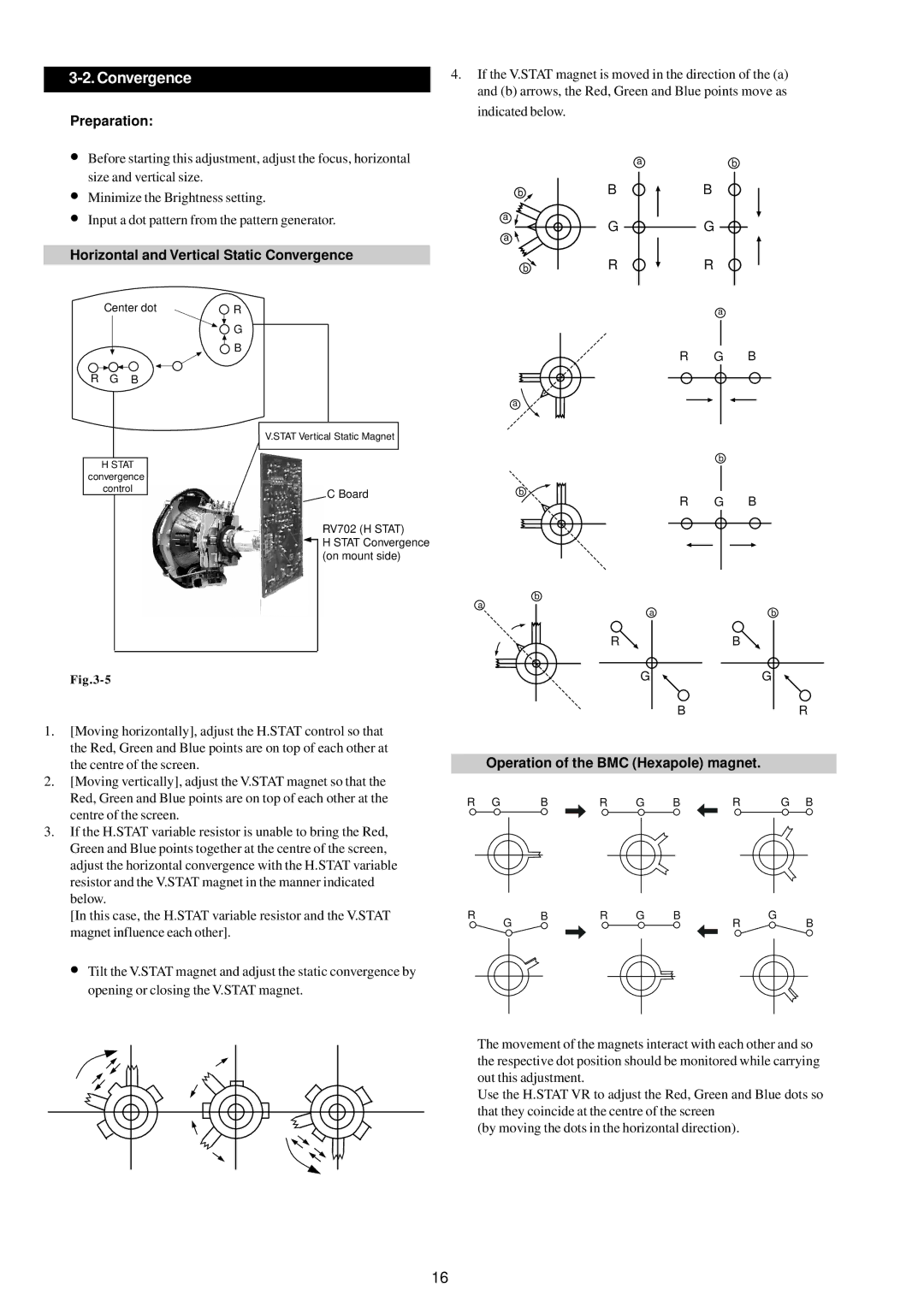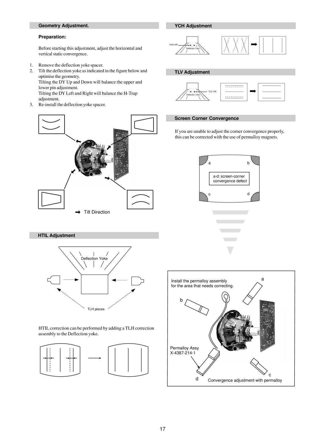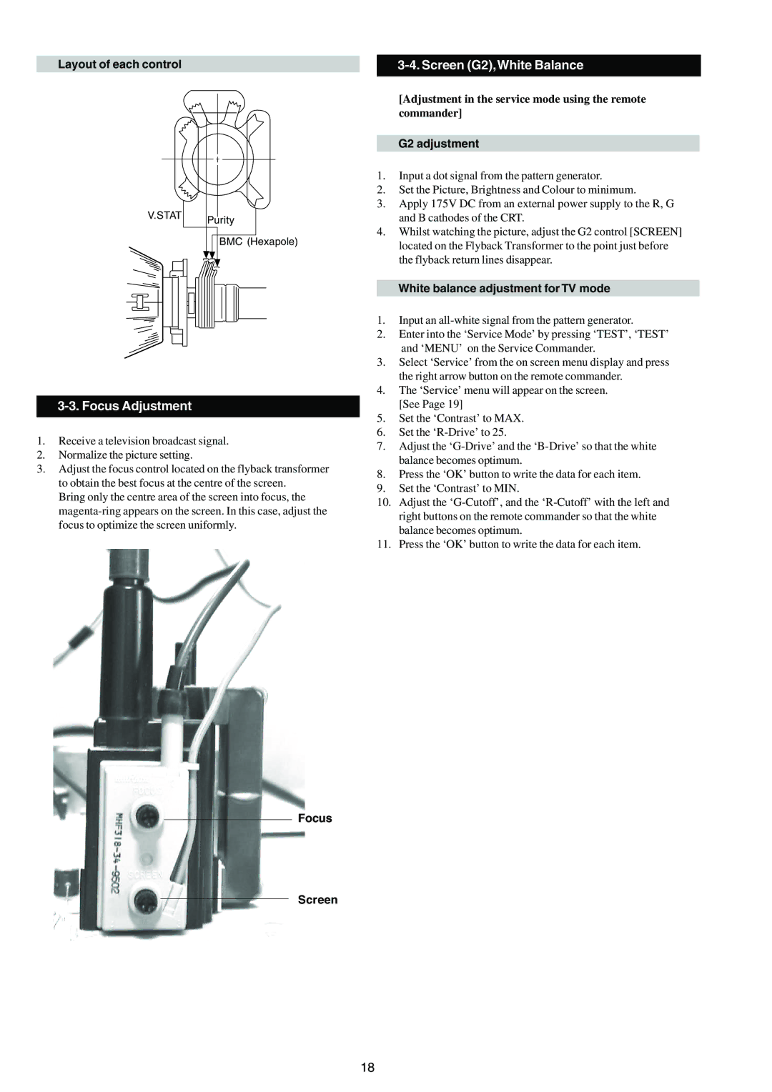
SECTION 4 CIRCUIT ADJUSTMENTS
4-1. Electrical Adjustments
Service adjustments to this model can be performed using the suppliedemote Commander
How to enter into the Service Mode
1.Turn on the main power switch and enter into the
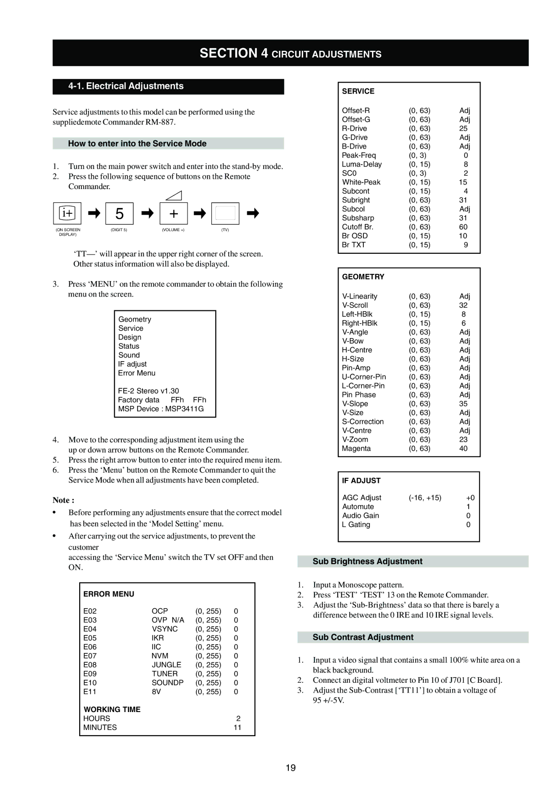
2.Press the following sequence of buttons on the Remote Commander.
i+ | 5 | + |
|
(ON SCREEN | (DIGIT 5) | (VOLUME +) | (TV) |
DISPLAY) |
|
|
|
3.Press ‘MENU’ on the remote commander to obtain the following menu on the screen.
Geometry
Service
Design
Status
Sound
IF adjust
Error Menu
Factory data FFh FFh
MSP Device : MSP3411G
4.Move to the corresponding adjustment item using the up or down arrow buttons on the Remote Commander.
5.Press the right arrow button to enter into the required menu item.
6.Press the ‘Menu’ button on the Remote Commander to quit the Service Mode when all adjustments have been completed.
Note :
•Before performing any adjustments ensure that the correct model has been selected in the ‘Model Setting’ menu.
•After carrying out the service adjustments, to prevent the customer
accessing the ‘Service Menu’ switch the TV set OFF and then ON.
ERROR MENU |
|
|
|
E02 | OCP | (0, 255) | 0 |
E03 | OVP N/A | (0, 255) | 0 |
E04 | VSYNC | (0, 255) | 0 |
E05 | IKR | (0, 255) | 0 |
E06 | IIC | (0, 255) | 0 |
E07 | NVM | (0, 255) | 0 |
E08 | JUNGLE | (0, 255) | 0 |
E09 | TUNER | (0, 255) | 0 |
E10 | SOUNDP | (0, 255) | 0 |
E11 | 8V | (0, 255) | 0 |
WORKING TIME |
|
|
|
HOURS |
|
| 2 |
MINUTES |
|
| 11 |
|
|
|
|
SERVICE |
|
|
(0, 63) | Adj | |
(0, 63) | Adj | |
(0, 63) | 25 | |
(0, 63) | Adj | |
(0, 63) | Adj | |
(0, 3) | 0 | |
(0, 15) | 8 | |
SC0 | (0, 3) | 2 |
(0, 15) | 15 | |
Subcont | (0, 15) | 4 |
Subright | (0, 63) | 31 |
Subcol | (0, 63) | Adj |
Subsharp | (0, 63) | 31 |
Cutoff Br. | (0, 63) | 60 |
Br OSD | (0, 15) | 10 |
Br TXT | (0, 15) | 9 |
|
|
|
|
|
|
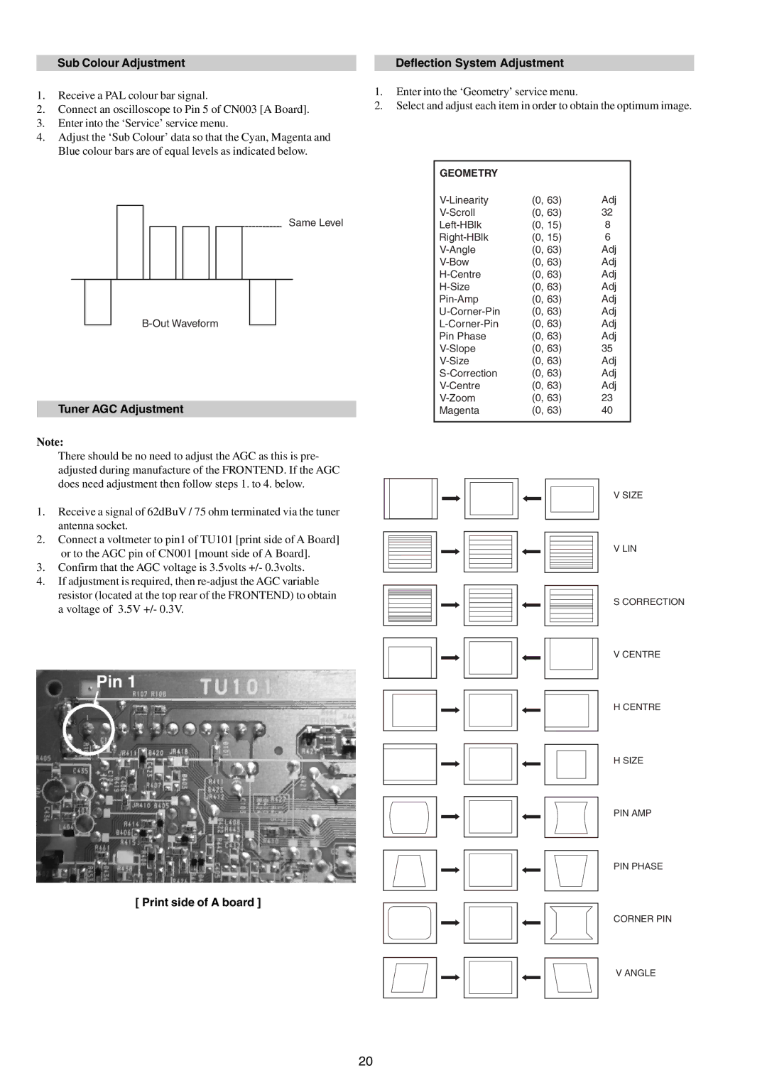
GEOMETRY |
|
|
(0, 63) | Adj | |
(0, 63) | 32 | |
(0, 15) | 8 | |
(0, 15) | 6 | |
(0, 63) | Adj | |
(0, 63) | Adj | |
(0, 63) | Adj | |
(0, 63) | Adj | |
(0, 63) | Adj | |
(0, 63) | Adj | |
(0, 63) | Adj | |
Pin Phase | (0, 63) | Adj |
(0, 63) | 35 | |
(0, 63) | Adj | |
(0, 63) | Adj | |
(0, 63) | Adj | |
(0, 63) | 23 | |
Magenta | (0, 63) | 40 |
|
|
|
|
|
|
IF ADJUST |
|
|
AGC Adjust | +0 | |
Automute |
| 1 |
Audio Gain |
| 0 |
L Gating |
| 0 |
|
|
|
Sub Brightness Adjustment
1.Input a Monoscope pattern.
2.Press ‘TEST’ ‘TEST’ 13 on the Remote Commander.
3.Adjust the
Sub Contrast Adjustment
1.Input a video signal that contains a small 100% white area on a black background.
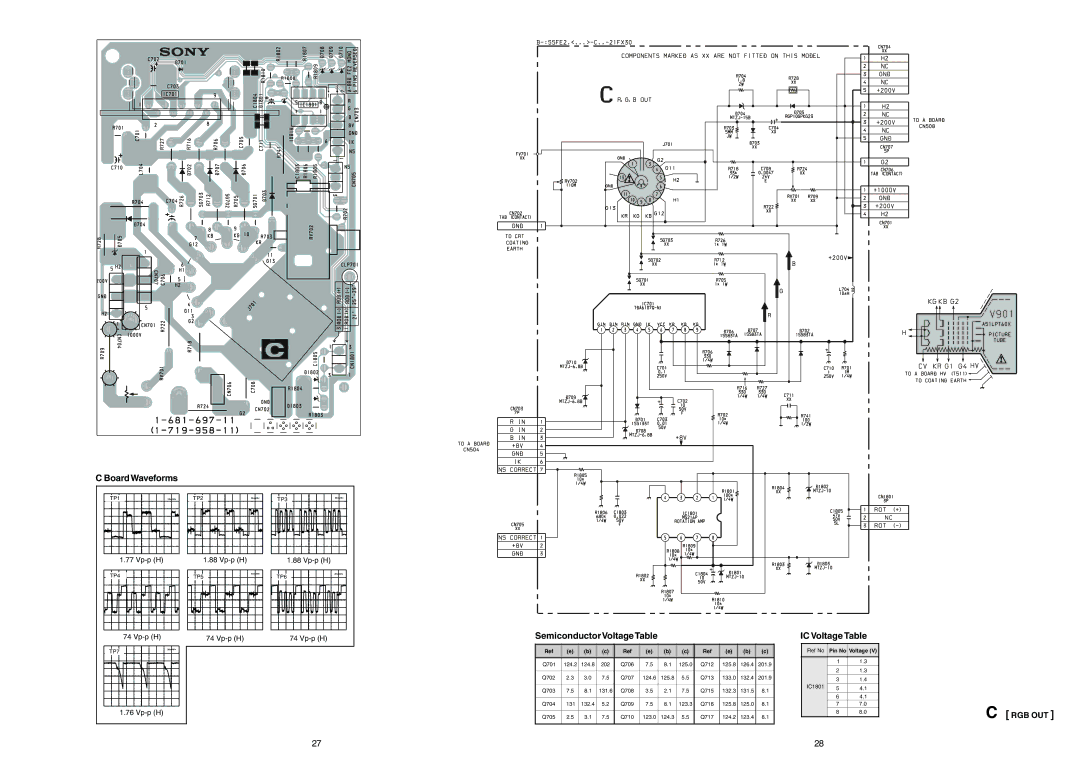
2.Connect an digital voltmeter to Pin 10 of J701 [C Board].
3.Adjust the
19
