ELECTRICAL ADJUSTMENTS
2-13: TINT
1.Receive the NTSC color bar pattern. (Audio Video Input)
2.Using the remote control, set the brightness and contrast to normal position.
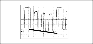
3.Connect the oscilloscope to TP024.
4.Activate the adjustment mode display of Fig.
5.Press the VOL. +/- button on the remote control until the section "A" becomes a straight line. (Refer to Fig.
"A"
Fig.
2-14: CONTRAST CENT
1.Activate the adjustment mode display of Fig.
2.Press the VOL. +/- button on the remote control until the contrast step No. becomes "35".
3.Receive a broadcast and check if the picture is normal.
4.Set to the AV mode. Then perform the above adjustments 1~3.
2-15: Confirmation of Fixed Value (Step No.)
Please check if the fixed values of the each adjustment items are set correctly referring below.
NO. FUNCTION | RF | AV | |
02 | AGC GAIN | 00 | |
04 | R CUTOFF | 00 | |
06 | G CUTOFF | 00 | |
07 | B DRIVE | 45 | |
09 | V POSI (50) | 08 | |
10 | V POSI (60) | 00 | |
18 | BRIGHT MAX | 40 | 40 |
19 | BRIGHT MIN | 09 | 09 |
20 | TINT | 32 | ADJ. |
21 | SHARP | 02 | 02 |
23 | CONTRAST MAX | 50 | 50 |
24 | CONTRAST MIN | 10 | 10 |
26 | COLOR MAX | 50 | 50 |
27 | COLOR MIN | 10 | 10 |
30 | M B CUT OFF | 127 | |
31 | CVBS OUT | 31 | |
32 | APR THRESHOLD | 00 | |
33 | BELL FILTER | 10 | |
34 | BANDPASS | 00 | |
35 | H POSI OSD | 118 | |
36 | V POSI OSD | 50 | |
37 | H POSI TEXT | 122 | |
38 | V POSI TEXT | 58 | |
*To check for the fixed values of the RF (60Hz), indicate the adjustment mode screen while input the 60Hz video signal.