MICON/TUNER
0.5µs
1V
1
10ms
1V
2
20µs
1V
3
20µs
1V
4
50µs
100mV
5
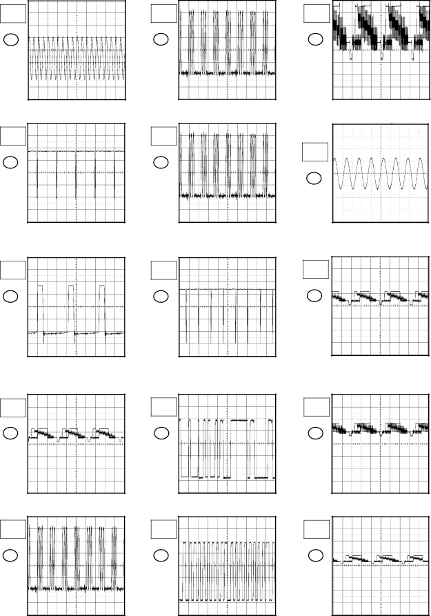
WAVEFORMS
50µs
100mV
6
50µs
100mV
7
50µs
0.5V
8
0.2ms
1V
9
0.2ms
1V
10
IF/CHROMA
20µs
0.5V
11
2ms
200mV
12
20µs
1V
13
20µs
1V
14
20µs
1V
15
NOTE: The following waveforms were measured at the point of the corresponding balloon number in the schematic diagram.