INSTALLATION
2.2 Connecting the wiring
Refer to Figure
Caution: For DC power supply use, make sure the polarity is correct to avoid malfunction and / or camera damage.
2.3 Mounting the Camera
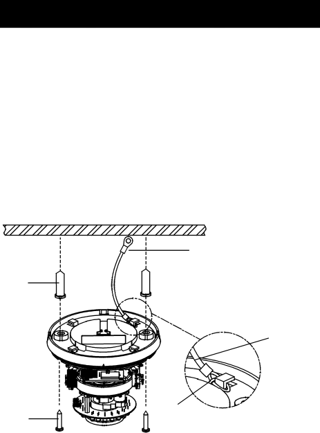
1.Attach the mounting template to the wall or ceiling.
2.Drill two holes, then insert the screw anchors (#1) into the holes.
3.Secure the bottom case to the wall or ceiling with the TP4 x 15 mm tapping screws supplied (#2).
4.To prevent the camera from falling off, ensures it is connected to a firm place (ceiling slab or channel) using a Safety Wire (fall prevention wire#3 is not supplied).
Note: Depending on the material of your mounting surface, you may require different screws and anchors than those supplied.
③
①
Plastic Band
②
Safety Wire (fall prevention wire#3 is not supplied).
Please tighten a safety wire using plastic band on a firm
place as photo.
Safety Wire
1.Screw anchors (x2), supplied
2.TP4 x 15 tapping screws (x2), supplied
3.Safety Wire(fall prevention wire, not supplied)
Figure 2-2 Camera installation
6