

KD-S6350/KD-S590
Installation/Connection Manual
Manual de instalación/conexión
Manuel d’installation/raccordement
[J]
ENGLISH |
| ESPAÑOL |
|
|
|
V 1002KKSFLEJEIN
J C
EN, SP, FR
FRANÇAIS
•This unit is designed to operate on 12 V DC, NEGATIVE ground electrical systems.
•Esta unidad está diseñada para funcionar con 12 V de CC, con sistemas eléctricos de masa NEGATIVA.
•Cet appareil est conçu pour fonctionner sur des sources de courant continu de 12 V à masse NEGATIVE.
INSTALLATION (IN-DASH
MOUNTING)
•The following illustration shows a typical installation. However, you should make adjustments corresponding to your specific car. If you have any questions or require information regarding installation kits, consult your JVC car audio dealer or a company supplying kits.
INSTALACION (MONTAJE EN EL TABLERO DE INSTRUMENTOS)
•La siguiente ilustración muestra una instalación típica. Sin embargo usted deberá efectuar los ajustes correspondientes a su automóvil. Si tiene alguna pregunta o necesita información acerca de las herramientas para instalación, consulte con su concesionario de JVC de equipos de audio para automóviles o a una compañía que suministra tales herramientas.
INSTALLATION (MONTAGE DANS LE TABLEAU DE BORD)
•L’illustration suivante est un exemple d’installation typique. Cependant, vous devez faire les ajustements correspondant à votre voiture particulière. Si vous avez des questions ou avez besoin d’information sur des kits d’installation, consulter votre revendeur d’autoradios JVC ou une compagnie d’approvisionnement.
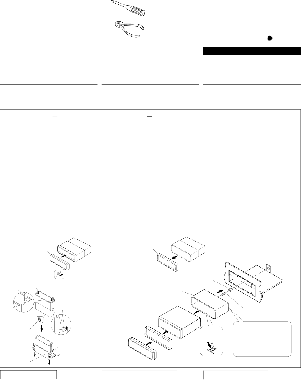
1Before mounting: Press ![]()
![]()
![]() (Control Panel Release button) to detach the control panel if already attached.
(Control Panel Release button) to detach the control panel if already attached.
*When shipped from the factory, the control panel is packed in the hard case
2Remove the trim plate.
3Remove the sleeve after disengaging the sleeve locks. 1 Stand the unit.
Note: When you stand the unit, be careful not to damage the fuse on the rear.
2Insert the 2 handles between the unit and the sleeve, as illustrated, to disengage the sleeve locks.
3Remove the sleeve.
Note: Be sure to keep the handles for future use after installing the unit.
4Install the sleeve into the dashboard.
*After the sleeve is correctly installed in the dashboard, bend the appropriate tabs to hold the sleeve firmly in place, as illustrated.
5Fix the mounting bolt to the rear of the unit’s body and place the rubber cushion over the end of the bolt.
6Do the required electrical connections explained on the back of this instructions.
7Slide the unit into the sleeve until it is locked.
8Attach the trim plate.
9Attach the control panel.
1Antes de instalar: Pulse ![]()
![]()
![]() (soltar panel de control) para separar el panel de control si ya está unido.
(soltar panel de control) para separar el panel de control si ya está unido.
*Cuando se envía de la fábrica, el panel de control está embalado en el estuche duro.
2Retire la placa de guarnición.
3Retire la cubierta después de desenganchar los retenes de la cubierta.
1 Ponga la unidad vertical.
Nota: Al poner la unidad vertical, tenga cuidado de no dañar el fusible provisto en la parte posterior.
2Inserte las dos asas entre la unidad y la cubierta tal como en la ilustración y desenganche los retenes de la cubierta.
3Retire la cubierta.
Nota: Después de instalar la unidad, asegúrese de guardar las asas para uso futuro.
4Instale la cubierta en el tablero de instrumentos.
*Después de que la cubierta esté correctamente instalada en el tablero de instrumentos, doble las lengüetas correspondientes para sostener la cubierta firmemente en su lugar, tal como se muestra.
5Fixe el perno de montaje ou la parte trasera del cuerpo de la unidad y coloque el cojín de goma sobre el extremo del perno.
6Realice las conexiones eléctricas requeridas en base a las explicaciones que figuran en la parte de atrás de estas instrucciones.
7Deslice la unidad dentro de la cubierta hasta que quede trabada.
8Coloque la placa de guarnición.
9Coloque el panel de control.
1Avant le montage: Appuyez sur ![]()
![]()
![]() (déblocage du panneau de commande) pour éventuellement détacher le panneau de commande.
(déblocage du panneau de commande) pour éventuellement détacher le panneau de commande.
*Lorsque ce panneau de commande sort d’usine, il est rangé dans un étui de transport.
2Retirer la plaque d’assemblage.
3Libérer les verrous du manchon et retirer le manchon.
1 Poser l’appareil à la verticale.
Remarque: Lorsque vous mettez l’appareil à la verticale, faire attention de ne pas endommager le fusible situé sur le fond.
2Insérer les 2 poignées entre l’appareil et le manchon comme indiqué pour désengagé les verrous de manchon.
3Retirer le manchon.
Remarque: S'assurer de garder les poignées pour une utilisation ultérieur, après l'installation de l'appareil.
4Installer le manchon dans le tableau de bord.
*Après installation correcte du manchon dans le tableau de bord, plier les bonnes pattes pour maintenir fermement le manchon en place, comme montré.
5Monter le boulon de montage sur l’arrière du corps de l’appareil puis passer l’amortisseur en caoutchouc sur l’extrémité du boulon.
6Réalisez les connexions électriques expliquées au dos de cette page.
7Faire glisser l’appareil dans le manchon jusqu’à ce qu’il soit verrouillé.
8Remonter la plaque d’assemblage.
9Remonter le panneau de commande.
1 Control Panel | 2 Trim plate |
Panel de control | Placa de guarnición |
Panneau de command | Plaque d’assemblage |
3 Handle
Manija
Poignée
Lock Plate
Placa de bloqueo
Plaque de verrouillage
Slot
Ranura
Fente
Fuse | 8 |
| |
Fusible |
|
Fusible |
|
| 9 |
Sleeve | Control Panel |
Cubierta | Panel de control |
Manchon | Panneau de command |
|
| Dashboard |
| ||
|
| Tablero de instrumentos | |||
|
| Tableau de bord | |||
| Rubber cushion |
|
|
|
|
| Cojín de goma | 184 |
|
|
|
| Amortisseur en caoutchouc | mm |
|
| |
|
|
|
| ||
| 4 |
|
|
| |
Sleeve | 5 | 53 | mm | ||
|
|
| |||
Cubierta |
|
|
| ||
Manchon | 7 |
|
| ||
|
|
| Mounting bolt | ||
|
|
|
| ||
|
|
|
| Perno de montaje | |
|
|
|
| Boulon de montage | |
| 4 * |
| 6 |
|
|
|
| See “ELECTRICAL CONNECTIONS”. | |||
Véase “CONEXIONES ELECTRICAS”.
ELECTRIQUES” .
Trim plate
Placa de guarnición
Plaque d’assemblage
TROUBLESHOOTING
LOCALIZACION DE AVERIAS
EN CAS DE DIFFICULTÉS
•The fuse blows.
* Are the red and black leads connected correctly?
•Power cannot be turned on. * Is the yellow lead connected?
•No sound from the speakers.
* Is the speaker output lead
•Sound is distorted.
*Is the speaker output lead grounded?
*Are the
•Unit becomes hot.
*Is the speaker output lead grounded?
*Are the
• El fusible se quema.
* ¿Están los conductores rojo y negro correctamente conectados?
•No es posible conectar la alimentación. * ¿Está el cable amarillo conectado?
•No sale sonido de los altavoces.
* ¿Está el cable de salida del altavoz cortocircuitado?
• El sonido presenta distorsión.
*¿Está el cable de salida del altavoz conectado a masa?
*¿Están los terminales
• La unidad se calienta.
*¿Está el cable de salida del altavoz conectado a masa?
*¿Están los terminales
• Le fusible saute.
*Les fils rouge et noir
•L’appareil ne peut pas être mise sous tension. * Le fil jaune
•Pas de son des
*Le fil de sortie de
• Le son est déformé.
*Le fil de sortie de
*Les bornes
• L’appareil devient chaud.
*Le fil de sortie de
*Les bornes
1