4.2.2 Pan Meter Adjustment
1.Turn on the power switch. There should be a slight noticeable change in the meter reading.
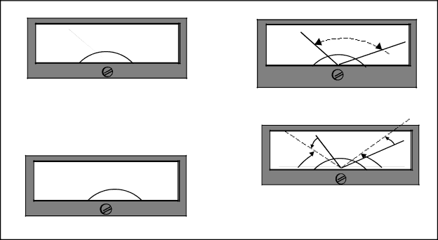
2.Activate the PAN LEFT switch and observe the pan meter reading. The AZL pan meter readout should approach “0” as the unit rotates. The unit will stop at the extreme left position. Note the meter
reading. For our example, let's assume the reading is 60° (see Fig. 5a).
3.Note the meter reading and activate the PAN RIGHT switch until the unit reaches the extreme
right position. Note the meter reading. For our ex- ample, lets assume the reading is 330° (see Fig.
5b).
4.These two meter readings define the “deflection range” of the meter (in our case 330 ° - 60° = 270°,
see Fig. 5c) and mirrors mechanical pan movement of the P/T between its extremes. This “range” must now be shifted (in our case, to the left) by adjust- ing the “center scale potentiometer” (PAN 1K pot, see Fig. 3) on the AZL
In our example:
360° - 270°/ 2 = 90°/ 2 = 45°
In other words, the entire range should be shifted to the left enough so that the difference between the deflection range reading made at the PAN LEFT operation and 0° and the difference between the PAN RIGHT operation and 360° are equal and have a value of 45°. In our example, then, we require the PAN RIGHT meter reading to be (360°- 45°), or 315°. The current meter reading is at 330°, so you must now adjust the “center scale pot” (PAN 1K pot, see Fig. 3) until you obtain a meter read- ing of 315°. This shifts or “rotates” the entire de- flection range for a balanced meter deflection at both ends as indicated in Figure 5d.
5.Now adjust the “full scale potentiometer” (PAN
5K Pot, see Fig. 3) on the back of the AZL unit to obtain a reading of 360°.
6.Finally, activate the PAN LEFT switch until the unit reaches the extreme left position. Verify the meter reading to be “0” degrees. Make minor ad- justments as necessary.
|
| PAN LEFT |
|
|
| 0 |
|
(a) |
| 60 |
|
0 | 360 | 0 | |
| 0 | ||
|
| ||
|
|
|
| PAN RIGHT |
|
|
(b) | 330 | 0 |
|
360 |
| ||
0 |
| 0 | |
0 |
| ||
|
|
|
| Deflection Range = 270 | 0 |
| |
(c) | 0 | 360 | 0 | ||
0 | |||||
|
| ||||
|
|
| |||
0
|
|
|
| 315 |
| 15 | 0 | 15 | 0 |
|
| |||
|
|
| ||
(d) |
|
| 0 |
|
0 |
| 360 | 0 | |
| 0 |
| ||
|
|
| ||
|
|
| 0 |
|
|
|
| 45 |
|
Center scale potentiometer adjustment for shifting deflection range for balanced reading.
Figure 5. Meter Adjustment
Pelco Manual C521M (6/95) | 5 |