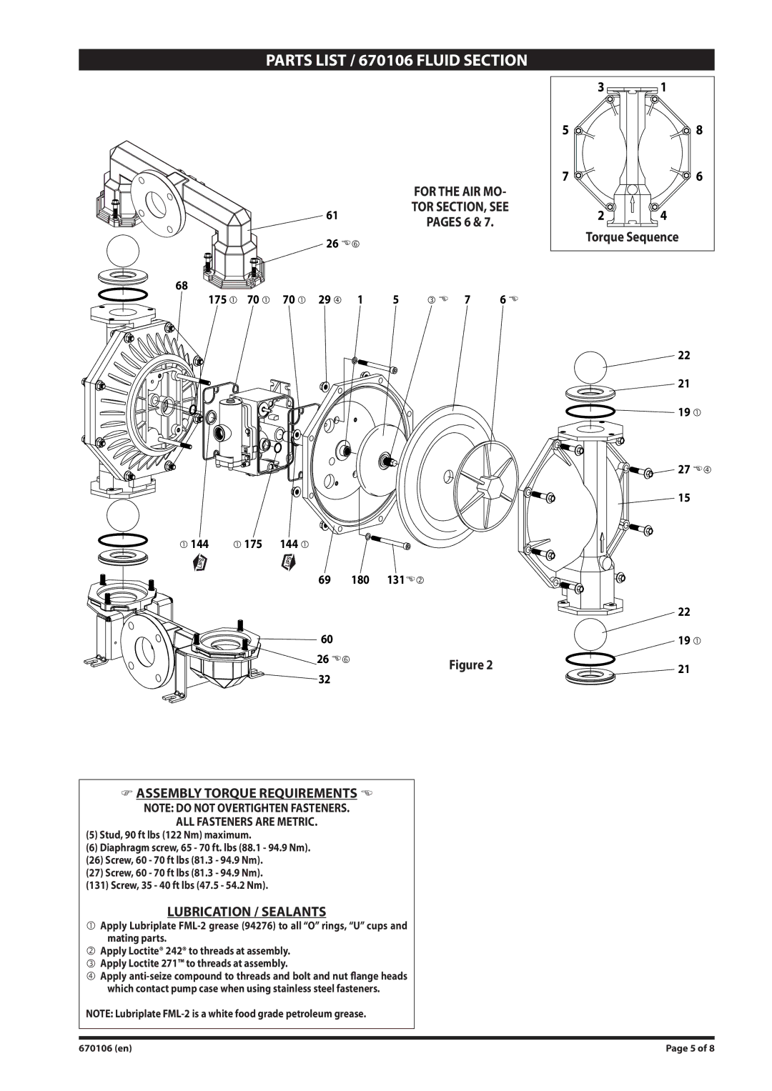
PARTS LIST / 670106 FLUID SECTION
PARTS LIST
Item | Description (size) | Qty | Part No. | [Mtl] |
|
|
|
|
|
1 | Rod | (1) | 94984 | [C] |
|
|
|
|
|
5 | Backup Washer | (2) | 66167 | [SS] |
|
|
|
|
|
6 | Diaphragm Screw | (2) | 94094 | [SS] |
|
|
|
|
|
7 | Diaphragm | (2) | [Sp] | |
15 | Fluid Cap | (2) | 94107 | [SS] |
|
|
|
|
|
19 | “O” Ring (3/16” x 5” o.d.) | (4) | [T] | |
21 | Seat | (4) | 94113 | [SS] |
|
|
|
|
|
22 | Ball | (4) | [T] | |
26 | Screw (M12 x 1.75 - 6g x 45 mm) | (12) | [SS] | |
|
|
|
|
|
27 | Screw (M12 x 1.75 - 6g x 60 mm) | (16) | 94991 | [SS] |
|
|
|
|
|
29 | Nut (M12 x 1.75 - 6h) | (16) | 95053 | [SS] |
|
|
|
|
|
9Indicates items included in 637421 air section repair kit.
FLUID SECTION DISASSEMBLY
1.Remove top manifold(s).
2.Remove (22) balls, (19) “O” rings and (21) seats.
3.Remove (15) fluid caps.
4.Remove (6) diaphragm screws, (7) diaphragms and (5) backup washers.
NOTE: Do not scratch or mar the surface of (1) diaphragm rod.
FLUID SECTION REASSEMBLY
SERVICE NOTE: ARO pn
yReassemble in reverse order.
yClean and inspect all parts. Replace worn or damaged parts with new parts as required.
yLubricate (1) diaphragm rod and (144) “U” cup with Lubri- plate
yBe certain the diaphragm assembly bottoms out on the
(1) rod.
y
Item | Description (size) |
| Qty | Part No. | [Mtl] | |||
|
|
|
|
|
| |||
32 | Leg |
| (2) | [SS] | ||||
|
|
|
|
|
| |||
43 | Ground Lug (see page 7) |
| (1) | 93004 | [Co] | |||
|
|
|
|
|
| |||
60 | Inlet Manifold |
| (1) | 96785 | [SS] | |||
|
|
|
|
|
| |||
61 | Outlet Manifold |
| (1) | 96784 | [SS] | |||
|
|
|
|
|
| |||
68 | Air Cap |
| (1) | [A] | ||||
|
|
|
|
|
| |||
69 | Air Cap |
| (1) | [A] | ||||
|
|
|
|
|
| |||
9 70 | Gasket |
| (2) | 94100 | [B] | |||
131 | Screw (M10 x 1.5 - 6g x 120 mm) |
| (4) | 94531 | [C] | |||
|
|
|
|
|
| |||
9 144 | “U” Cup (3/16” x |
| (2) | [B] | ||||
9 175 | “O” Ring (3/32” x 1” o.d.) |
| (2) | [B] | ||||
9 180 | Gasket (0.406” i.d. x 0.031” thick) |
| (4) | 94098 | [Co] | |||
|
|
|
|
|
|
|
|
|
|
|
|
|
| MATERIAL CODE |
|
| |
|
|
| [A] | = Aluminum |
|
| ||
|
|
| [B] | = Nitrile |
|
| ||
|
|
| [C] | = Carbon Steel |
|
| ||
|
|
| [Co] | = Copper |
|
| ||
|
|
| [Sp] | = Santoprene |
|
| ||
|
|
| [SS] | = Stainless Steel |
|
| ||
|
|
| [T] | = PTFE |
|
| ||
|
|
|
|
|
|
|
|
|
1.Apply Loctite 271 Threadlocker to thread (3) on (5) Back- up Washer.
2.Insert (7) Diaphragm insuring seal bead on (7) Diaphragm is in the groove on (5)
3.Thread (6) Diaphragm Screw onto the stud on (5) Back-up Washer.
Applying a light coating of Lubriplate
Diaphragm Assembly
ASSEMBLING DIAPHRAGM ASSEMBLY
7
56
3
Diaphragm assembly: (3) Thread, (5)
1
1.Screw the two Diaphragm Assemblies to (1) Rod.
2.Tighten Diaphragm Assemblies to
Page 4 of 8 | 670106 (en) |
