JBL AVR480 manual

Page 35

change the device selected by the AVR480 or the remote. Note, however, that the remote is factory-preset so that the Transport Controls w are pro- grammed with the codes for JBL DVD players, and no further programming is required to use a JBL DVD player when the AVR controls are active after the AVR Selector g has been pressed. To pro- gram the remote for Transport Control Punch-Through, follow these steps:

1.Press the Input Selector f for the device you will be using (e.g., TV) when you wish to have Transport Control Punch-Through active and the Mute Button 37 at the same time until the red light appears under the Input Selector f and the Program Indicator c flashes amber.

2.Press the Play Button w. The Program Indicator c will stop flash- ing and stay amber.

3.Press and release the Input Selector Button f for the device whose trans- port mechanism will be controlled (e.g., DVD, CD). The Program Indicator c will blink green three times and then go out to confirm the data entry.

EXAMPLE: To control the transport of a VCR while the remote is set to control the TV, first press the TV Input Selector

fand the Mute Button 37 at the same time. Next, release them and press the Play Button w, followed by the VID1/VCR Input Selector f.

NOTE: To remove the Channel Control Punch-Through and return the remote to its original configuration, repeat the steps shown above. However, press the same button in Steps 1 and 3.

Resetting the Remote Memory

As you add components to your home the- ater system, occasionally you may wish to totally reprogram the remote control with- out the confusion of any commands, macros or ”Punch-Through“ programming that you may have done. To do this, it is possible to reset the remote to the original factory defaults and command codes by following these steps. Note, however, that once the remote is reset, all commands or

codes that you have entered will be erased and will need to be reentered:

1.Press any of the Input Selector Buttons f and the “O” Button q at the same time until the Program Indicator c begins to flash amber.

2.Press the “3” Button q three times.

3.The red LED under the Input Selector f will go out and the Program Indicator c will stop flashing and turn green.

4.The Program Indicator c will remain green until the remote is reset. Note that this may take a while, depending on how many commands are in the memory and need to be erased.

5.When the Program Indicator c goes out, the remote has been reset to the factory settings.

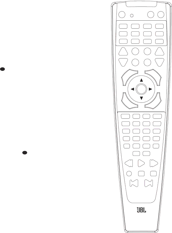
The diagram on this page shows the but- ton numbers used in the Function List tables on pages 36–37. Do not confuse these numbers with those used through- out the rest of this manual to indicate the specific buttons used to operate the AVR480’s functions. The key to those but- ton numbers, which are shown inside an oval, is found on page 12.

1


2

3

4

5

6

7

8

9

10

11

12

13

14

15

16

17

18

19

20

21

22

23

24


26


25


28


29


27


31


30


32

33

34

35

36

37

38

39

40

41

42

43

44

45

46

47

48

49

50

51

52


53

54


55

56

57

58

59

60

61


62

AVR480

35

Image 35
Contents AVR480 Introduction Important Safety InformationDeclaration of Conformity AVR480 AUDIO/VIDEO ReceiverWalked on or pinched, particularly at An electrician for replacementMultiple Digital Inputs and an Output Description and FeaturesIntroduction Unpacking Important Safety InformationSafety Information ‹/›Selector Buttons Set Button Delay Button Digital Input SelectorFRONT-PANEL Controls Optical and Coaxial Digital $ Volume Control Turn this knobFRONT-PANEL Information Display Speaker/Channel Input IndicatorsPreset Number/Sleep Timer P Preset Indicator Logic 7 Mode IndicatorsPage Optical Digital Audio Input REAR-PANEL ConnectionsCoaxial Digital Audio Output Coaxial Digital Audio InputDVD S-Video Input Video 2 Video Input Connect thisVideo 2 Audio Inputs Connect Video Monitor Outputs ConnectProgram Indicator This three-color Remote Control FunctionsAfter the Delay Button has been pressed Page Speaker Outputs to the respective speakers Installation and ConnectionsPanel. Note that the Optical Video Connection Notes Video 1 Output JacksVideo source to the Video Video 3 # Input Jacks DVD Video Input JacksMeters 6 feet behind the rear of the seating area Speaker PlacementSpeaker Selection Input Setup Settings to Be Made With Each Input UsedSystem Configuration To obtain the correct power cord for your areaInformation Display K Press the Set Button E Speaker SetupPress the Speaker Button Ô FNT Spkr will appear in the MainIcons in the Speaker/Channel Input Surround SetupSurround Mode Selector Button Buttons C % so that SUB LFE appears in the displaySdelay will appear in the Main Configuring Global SettingsDelay Settings To set the delay time, follow these stepsDisplay K. Press the ⁄/¤ Buttons Night Mode SettingsOutput Level Adjustment Adjust the Volume Control $Appears in the Main Information Until the desired surround modeOperation Basic OperationSource Selection 11 listening modes are available on the AVR480 Surround Mode SelectionUp/Down buttons Mute ButtonInput on the rear panel Digital Audio PlaybackDolby Digital Optical or Coaxial Input on the rear panel Digital Status IndicatorsSelecting a Digital Source PCM Audio PlaybackSurround Mode Chart Video 1 Outputs Night ModeWhen a Dolby Digital or DTS source Tape RecordingDisplay Brightness Memory BackupUsing the Volume Control $ Tuner Operation Auto Search Method Programming the Product CodesProgramming the Remote Direct Code EntryProgrammed Device Functions Macro ProgrammingTransport Control Punch-Through Volume Punch-ThroughChannel Control Punch-Through AVR480 Function List Direct Preset UpPreset Down Tape VCR VID1,3Device TV Hinari Saba Device VCR 054 076 154 047148 155 176 050 054 073012 044 047 090 141044 083 090 094 104 108 131 149 155Device CD Device DVD Device SAT Device Cable Setup Code NumberDevice Tape Troubleshooting Guide Processor ResetAVR480 Specifications Page
Related manuals
Manual 4 pages 51.39 Kb