JBL AVR480 manual FRONT-PANEL Information Display, Speaker/Channel Input Indicators

Page 8

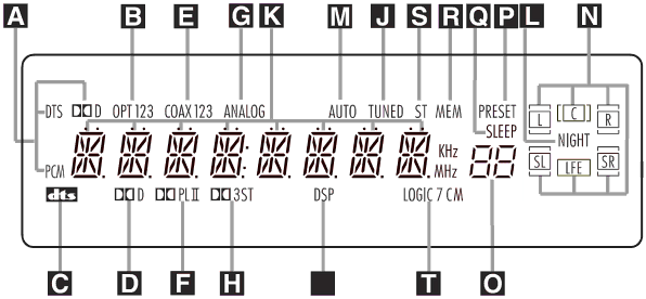
FRONT-PANEL INFORMATION DISPLAY

ABitstream Indicators B Optical Source Indicators C DTS Mode Indicator D Dolby Digital Indicator

E Coaxial Digital Input Indicators F Dolby Pro Logic II Indicator G Analog Input Indicator

ABitstream Indicators: When the input is a digital source, one of these indicators will light to display the specific type of signal in use.

BOptical Source Indicators: These indicators light to show when an Optical Digital Input has been selected.

CDTS Mode Indicator: This indicator lights when the DTS mode is selected.

DDolby Digital Indicator: This indica- tor lights when the Dolby Digital mode is selected.

ECoaxial Digital Input Indicators: These indicators light to show when a Coaxial Digital Input has been selected.

FDolby Pro Logic II Indicator: This indicator lights when one of the Dolby Pro Logic II modes has been selected.

GAnalog Input Indicator: This indica- tor lights when an analog input source has been selected.

HDolby 3 Stereo Indicator I DSP Mode Indicator J Tuned Indicator

K Main Information Display L Night Mode Indicator M Auto Indicator

N Speaker/Channel Input Indicators

HDolby 3 Stereo Indicator: This indi- cator lights when the Dolby 3 Stereo Mode has been selected. Only the ST (Stereo) portion of this indicator will light when “Surround Off” has been selected. Then all Surround Modes are turned off and the unit will play in pure stereo mode.

IDSP Mode Indicator: This indicator lights when any of the surround modes created by Digital Signal Processing, or DSP are in use. These modes include Hall 1, Hall 2, Theater and 5-Channel Stereo.

JTuned Indicator: This indicator lights when a station is being received with suffi- cient signal strength to provide acceptable listening quality.

KMain Information Display: This dis- play shows messages relating to the sta- tus, input source, surround mode, tuner, volume level or other aspects of the unit’s operation.

OPreset Number/Sleep Timer P Preset Indicator

Q Sleep Indicator R Memory Indicator S Stereo Indicator

T Logic 7 Mode Indicators

LNight Mode Indicator: This indica- tor lights when the AVR480 is in the Night mode, which preserves the dynamic range of digital program material at low volume levels.

MAuto Indicator: This indicator lights when the tuner’s Auto mode is in use.

NSpeaker/Channel Input Indicators: These indicators are multipurpose, indicat- ing either the speaker type selected for each channel or the incoming data-signal configuration. The left, center, right, right surround and left surround speaker indica- tors are composed of two boxes, while the subwoofer is a single box. When the let- ters flash, the digital input has been inter- rupted (see pages 20 and 27 for more information on the Channel Indicators).

OPreset Number/Sleep Timer: When the tuner is in use, these numbers indi- cate the specific preset memory location in use (see page 31 for more information on preset stations). When the Sleep func- tion is in use, these numbers show how many minutes remain before the unit goes into the Standby mode.

8

Image 8
Contents AVR480 Important Safety Information Declaration of ConformityAVR480 AUDIO/VIDEO Receiver IntroductionAn electrician for replacement Walked on or pinched, particularly atMultiple Digital Inputs and an Output Description and FeaturesIntroduction Unpacking Important Safety Information Safety Information ‹/›Selector Buttons Set Button Delay Button Digital Input SelectorFRONT-PANEL Controls $ Volume Control Turn this knob Optical and Coaxial DigitalSpeaker/Channel Input Indicators Preset Number/Sleep Timer P Preset IndicatorLogic 7 Mode Indicators FRONT-PANEL Information DisplayPage REAR-PANEL Connections Coaxial Digital Audio OutputCoaxial Digital Audio Input Optical Digital Audio InputVideo 2 Video Input Connect this Video 2 Audio Inputs ConnectVideo Monitor Outputs Connect DVD S-Video InputRemote Control Functions Program Indicator This three-colorAfter the Delay Button has been pressed Page Speaker Outputs to the respective speakers Installation and ConnectionsPanel. Note that the Optical Video 1 Output Jacks Video source to the Video Video 3 # Input JacksDVD Video Input Jacks Video Connection NotesMeters 6 feet behind the rear of the seating area Speaker PlacementSpeaker Selection Settings to Be Made With Each Input Used System ConfigurationTo obtain the correct power cord for your area Input SetupSpeaker Setup Press the Speaker Button ÔFNT Spkr will appear in the Main Information Display K Press the Set Button ESurround Setup Surround Mode Selector ButtonButtons C % so that SUB LFE appears in the display Icons in the Speaker/Channel InputConfiguring Global Settings Delay SettingsTo set the delay time, follow these steps Sdelay will appear in the MainNight Mode Settings Output Level AdjustmentAdjust the Volume Control $ Display K. Press the ⁄/¤ ButtonsUntil the desired surround mode Appears in the Main InformationOperation Basic OperationSource Selection Surround Mode Selection Up/Down buttonsMute Button 11 listening modes are available on the AVR480Input on the rear panel Digital Audio PlaybackDolby Digital Digital Status Indicators Selecting a Digital SourcePCM Audio Playback Optical or Coaxial Input on the rear panelSurround Mode Chart Night Mode When a Dolby Digital or DTS sourceTape Recording Video 1 OutputsDisplay Brightness Memory BackupUsing the Volume Control $ Tuner Operation Programming the Product Codes Programming the RemoteDirect Code Entry Auto Search MethodMacro Programming Programmed Device FunctionsTransport Control Punch-Through Volume Punch-ThroughChannel Control Punch-Through AVR480 Function List Preset Up Preset DownTape VCR VID1,3 DirectDevice TV Hinari Saba Device VCR 047 148 155 176050 054 073 054 076 154044 047 090 141 044 083 090 094104 108 131 149 155 012Device CD Device DVD Device SAT Device Cable Setup Code NumberDevice Tape Processor Reset Troubleshooting GuideAVR480 Specifications Page
Related manuals
Manual 4 pages 51.39 Kb