PARTS LIST
(V)T32N, (V)T32NB, (V)T32NR, (V)T32NRB (V)T32P, (V)T32PB, (V)T32PR, (V)T32PRB, CHDV32NR
33
PARTS LIST
(V)T32N, (V)T32NB, (V)T32NR, (V)T32NRB, (V)T32P, (V)T32PB, (V)T32PR, (V)T32PRB, CHDV32NR
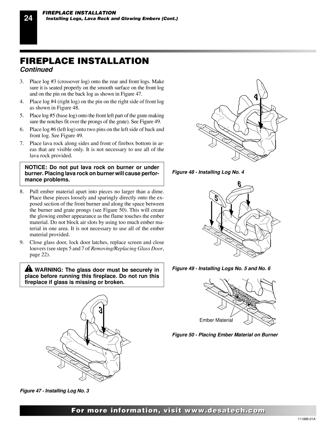
This list contains replaceable parts used in your fireplace. When ordering parts, follow the instructions listed under Replacement Parts on page 34 of this manual.
KEY | PART |
|
|
| KEY | PART |
|
|
NO. | NUMBER | DESCRIPTION | QTY. | NO. | NUMBER | DESCRIPTION | QTY. | |
|
|
|
|
|
|
|
|
|
1 | ** | Firebox Assembly | 1 |
| Base Grate Assembly | 1 | ||
2 | ** | Face Weldment | 1 |
| Burner | 1 | ||
3 | Door Assembly (T & CHDV Models Only) | 1 |
| Pilot Assembly (Natural) | 1 | |||
| Door Assembly (VT Models Only) | 1 |
|
| Pilot Assembly (Propane/LP) | 1 | ||
4 | Top Stamped Panel Assy | 1 |
| Burner Base Assembly | 1 | |||
|
| T32N/P, T32NB/PB Models |
|
| 27113 | Air Deflector | 1 | |
| Top Rolled Louver Assy T32NR/PR, | 1 |
| 10 | Burner Base Gasket | 1 | ||
|
| T32NRB/PRB & CHDV32NR Models |
|
| 11 | Rear Refractory Brick Panel |
| |
5 | Bottom Stamped Panel Assy | 1 |
|
|
| (B Models Only) | 1 | |
|
| T32N/P, T32NB/PB Models |
|
| 12 | Heat Shield | 1 | |
| Bottom Rolled Louver Assy (T32NR/PR, |
|
| 13 | Right Refractory Brick Panel |
| ||
|
| T32NRB/PRB, CHDV32NR Models) | 1 |
|
|
| (B Models Only) | 1 |
6 | Fireplace Top | 1 |
| 14 | Left Refractory Brick Panel |
| ||
7 | ** | Fireplace Top Insulation | 1 |
|
|
| (B Models Only) | 1 |
8 | ** | Fireplace Surround | 1 |
| 15 | 11418 | 2 | |
9 | Burner Assembly (Natural) | 1 |
| 16 | Screen | 2 | ||
| Burner Assembly (Propane/LP) | 1 |
| 17 | Screen Rod | 1 | ||
11102 | Screw | 2 |
| 18 | 14123 | Strain Relief | 1 | |
11105 | Screw #10 x 1/2 Zinc | 9 |
| 19 | 21171 | Gas | 2 | |
11179 | Screw | 4 |
| 20 | 24353 | Handy Box Assembly | 1 | |
11237 | Screw, Trilab M4 x 8mm | 1 |
| 21 | 24460 | Gas Conduit Assembly | 1 | |
14389 | Millivolt Valve (Natural) | 1 |
| 22 | Log Set | 1 | ||
| 14390 | Millivolt Valve (Propane/LP) | 1 |
| Front Log (Log 1) | 1 | ||
14492 | Piezo Ignitor | 1 |
| Rear Log (Log 2) | 1 | |||
14500 | Brass Fitting | 2 |
| Base Log (Log 3) | 1 | |||
14253 | Flexible Connector | 1 |
| Crossover Log (Log 4) | 1 | |||
14511 | Ignitor Bracket | 1 |
| Left Top Log (Log 5) | 1 | |||
14528 | Brass Elbow Fitting | 1 |
| Right Top Log (Log 6) | 1 | |||
Orifice (Natural) | 1 |
|
|
|
|
| ||
|
| PARTS AVAILABLE - NOT SHOWN |
| |||||
| 14514 | Orifice (Propane/LP) | 1 |
|
|
| ||
|
|
|
|
|
| |||
Aluminum Tubing Assy | 1 |
|
| 25487 | Lava Rock/Bag Assy | 1 | ||
26808 | Valve Bracket | 1 |
|
| ||||
|
| Conversion Kit (CHDV32NR only) | 1 | |||||
26827 | Switch Bracket | 1 |
|
| ||||
|
|
|
|
| ||||
|
|
|
|
|
|
|
|
|
** Not a field replaceable part.
![]() For more
For more![]()
![]()
![]() visit www.
visit www.![]()
![]()
![]() .com
.com![]()
![]()
![]()
![]()
![]()
![]()
