Intel DG33TL manual +5 V Standby Power Indicator LED

Page 23

Desktop Board Features

+5 V Standby Power Indicator LED

CAUTION

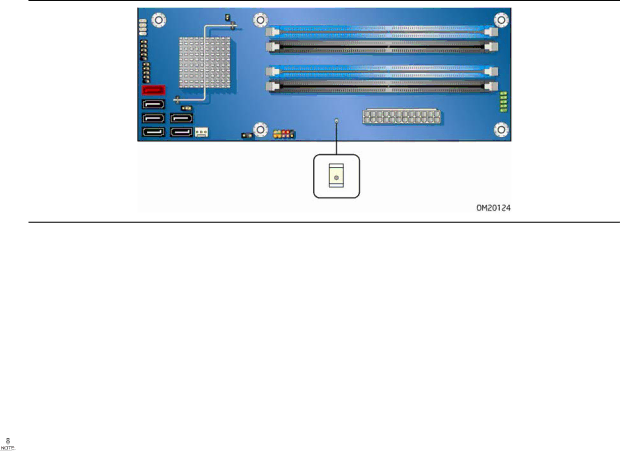
If the AC power has been switched off and the standby power indicator is still lit, disconnect the power cord before installing or removing any devices connected to the board. Failure to do so could damage the board and any attached devices.

The Desktop Board’s standby power indicator, shown in Figure 3, is lit when there is standby power still present on the board even when the computer appears to be off. For example, when this LED is lit, standby power is still present at the memory module sockets and the PCI bus connectors.

Figure 3. Location of the Standby Power Indicator

Related Links:

For more information on standby current requirements for the Desktop Board, refer to the Technical Product Specification by going to the following link, finding the product, and selecting Product Documentation from the left-hand menu:

http://support.intel.com/support/motherboards/desktop/

Wake from USB

NOTE

Wake from USB requires the use of a USB peripheral that supports Wake from USB.

USB bus activity wakes the computer from an ACPI S3 state.

PME# Signal Wake-up Support

When the PME# signal on the PCI bus is asserted, the computer wakes from an ACPI S3, S4, or S5 state.

23

Image 23
Contents Intel Desktop Board DG33TL Product Guide Disclaimer Revision HistoryFCC Declaration of Conformity Canadian Department of Communications Compliance StatementDocument Organization PrefaceIntended Audience Use Only for Intended ApplicationsTerminology Box ContentsContents Updating the Bios Regulatory Compliance ContentsTables Feature Summary Desktop Board FeaturesHardware Power ManagementSupported Operating Systems Related LinksDesktop Board Components Desktop Board FeaturesLabel Description Main Memory ProcessorType Timing Intel G33 Express ChipsetGMA 3100 Graphics Controller Intel G33 Graphics SubsystemDVI/VGA Port Status PCI Express x16 Connector DVI Port VGA PortAudio Subsystem LAN Subsystem RJ-45 LAN Connector LEDsLegacy Input/Output I/O Controller LED Color LED State Indicates Hi-Speed USB 2.0 SupportEnhanced IDE Interface Expandability Serial ATA and IDE Auto ConfigurationPCI and PCI Express* Auto Configuration Serial ATAHardware Monitoring and Fan Speed Control Hardware Management FeaturesSecurity Passwords Hardware Support Power Management FeaturesChassis Intrusion Fan Headers +5 V Standby Power Indicator LED Energy STAR* Qualified BatterySpeaker Real-Time ClockBefore You Begin Installing and Replacing Desktop Board ComponentsObserve Safety and Regulatory Requirements Installation PrecautionsPrevent Power Supply Overload Installing and Replacing Desktop Board Components Installing the I/O ShieldDesktop Board DG33TL Mounting Screw Hole Locations Installing and Removing the Desktop BoardInstalling a Processor Installing and Removing a ProcessorLift the Load Plate Remove the Processor from the Protective Processor Cover Close the Load Plate Installing the Processor Fan Heat SinkConnecting the Processor Fan Heat Sink Cable Removing the Processor Installing and Removing MemoryDual Channel Memory Configuration with Two DIMMs Guidelines for Dual Channel Memory ConfigurationThree DIMMs Use DDR2 DIMMs Installing DIMMsInstalling a Dimm Removing DIMMs Installing a PCI Express x16 Card Installing and Removing a PCI Express x16 CardRemoving a PCI Express x16 Card Removing the PCI Express x16 CardConnecting the IDE Cable Connecting the IDE Cable Connecting a Serial ATA Cable Connecting the Serial ATA Sata CablesConnecting the External Serial ATA Adapter Bracket Installing the External Serial ATA Adapter BracketInternal Headers Connecting to the Internal HeadersIeee 1394a Signal Header Names Connecting to the HD Audio Link HeaderConnecting to the Ieee 1394a Header HD Audio Link Header Signal NamesPin Signal Name Ground Connecting to the Consumer IR CIR HeadersFront Panel CIR Receiver Input Header Signal Names Back Panel CIR Header Emitter Output Header Signal NamesConnecting to the Alternate Front Panel Power LED Header Connecting to the Serial Port HeaderConnecting to the Chassis Intrusion Header Front Panel Header Connecting to the Front Panel HeaderConnecting to the USB 2.0 Headers USB 2.0 Header Signal NamesBack Panel Audio Connectors Connecting to the Flexible Audio SystemConnecting Chassis Fan Cables Connecting Chassis Fan and Power Supply CablesConnecting Power Supply Cables Connecting Supply Power CablesLocation of the Bios Configuration Jumper Block Setting the Bios Configuration JumperJumper Setting Mode Description Jumper Settings for the Bios Setup Program ModesClearing Passwords Precaution Replacing the BatteryΠροσοχή Vigyazat Uyari Removing the Battery Intel Desktop Board DG33TL Product Guide Updating the Bios with the Intel Express Bios Update Utility Updating the BiosUpdating the Bios with the ISO Image Bios Update File Obtaining the Bios Update FileUpdating the Bios Updating the Bios with the Iflash Memory Update UtilityRecovering the Bios Creating Your RAID Set Configuring for RAID Intel Matrix Storage TechnologyConfiguring the Bios for Intel Matrix Storage Technology Setting Up a RAID Ready System Bios Error Messages Error Messages and IndicatorsBios Beep Codes Bios Error MessagesIntel Desktop Board DG33TL Product Guide Regulatory Compliance Safety RegulationsPlace Battery Marking Safety RegulationsEuropean Union Declaration of Conformity Statement Regulatory Compliance Español Product Ecology StatementsRecycling Considerations DeutschRussian FrançaisMalay PortugueseTürkçe Lead-Free Desktop BoardLead-Free Board Markings EMC Regulations EMC RegulationsEnsure Electromagnetic Compatibility EMC Compliance Product Certification Markings Product CertificationsBoard-Level Certification Markings Europe Chassis and Component CertificationsIntel Desktop Board DG33TL Product Guide