Intel DG33TL manual Lift the Load Plate

Page 30

Intel Desktop Board DG33TL Product Guide

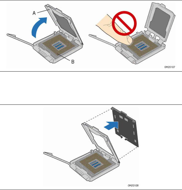
3. Lift the load plate (Figure 7, A). Do not touch the socket contacts (Figure 7, B).

Figure 7. Lift the Load Plate

4.Remove the plastic protective socket cover from the load plate (Figure 8). Do not discard the protective socket cover. Always replace the socket cover if the processor is removed from the socket.

Figure 8. Remove the Protective Socket Cover

30

Image 30
Contents Intel Desktop Board DG33TL Product Guide Canadian Department of Communications Compliance Statement Revision HistoryFCC Declaration of Conformity DisclaimerUse Only for Intended Applications PrefaceIntended Audience Document OrganizationBox Contents TerminologyContents Updating the Bios Contents Regulatory ComplianceTables Desktop Board Features Feature SummaryRelated Links Power ManagementSupported Operating Systems HardwareDesktop Board Features Desktop Board ComponentsLabel Description Processor Main MemoryIntel G33 Express Chipset Type TimingIntel G33 Graphics Subsystem GMA 3100 Graphics ControllerPCI Express x16 Connector DVI Port VGA Port Audio SubsystemDVI/VGA Port Status RJ-45 LAN Connector LEDs Legacy Input/Output I/O ControllerLAN Subsystem Hi-Speed USB 2.0 Support Enhanced IDE InterfaceLED Color LED State Indicates Serial ATA Serial ATA and IDE Auto ConfigurationPCI and PCI Express* Auto Configuration ExpandabilityHardware Management Features Security PasswordsHardware Monitoring and Fan Speed Control Power Management Features Chassis IntrusionHardware Support Fan Headers +5 V Standby Power Indicator LED Real-Time Clock BatterySpeaker Energy STAR* QualifiedInstalling and Replacing Desktop Board Components Before You BeginInstallation Precautions Prevent Power Supply OverloadObserve Safety and Regulatory Requirements Installing the I/O Shield Installing and Replacing Desktop Board ComponentsInstalling and Removing the Desktop Board Desktop Board DG33TL Mounting Screw Hole LocationsInstalling and Removing a Processor Installing a ProcessorLift the Load Plate Remove the Processor from the Protective Processor Cover Installing the Processor Fan Heat Sink Close the Load PlateConnecting the Processor Fan Heat Sink Cable Installing and Removing Memory Removing the ProcessorGuidelines for Dual Channel Memory Configuration Dual Channel Memory Configuration with Two DIMMsThree DIMMs Installing DIMMs Use DDR2 DIMMsInstalling a Dimm Removing DIMMs Installing and Removing a PCI Express x16 Card Installing a PCI Express x16 CardRemoving the PCI Express x16 Card Removing a PCI Express x16 CardConnecting the IDE Cable Connecting the IDE Cable Connecting the Serial ATA Sata Cables Connecting a Serial ATA CableInstalling the External Serial ATA Adapter Bracket Connecting the External Serial ATA Adapter BracketConnecting to the Internal Headers Internal HeadersHD Audio Link Header Signal Names Connecting to the HD Audio Link HeaderConnecting to the Ieee 1394a Header Ieee 1394a Signal Header NamesBack Panel CIR Header Emitter Output Header Signal Names Connecting to the Consumer IR CIR HeadersFront Panel CIR Receiver Input Header Signal Names Pin Signal Name GroundConnecting to the Serial Port Header Connecting to the Chassis Intrusion HeaderConnecting to the Alternate Front Panel Power LED Header USB 2.0 Header Signal Names Connecting to the Front Panel HeaderConnecting to the USB 2.0 Headers Front Panel HeaderConnecting to the Flexible Audio System Back Panel Audio ConnectorsConnecting Chassis Fan and Power Supply Cables Connecting Chassis Fan CablesConnecting Supply Power Cables Connecting Power Supply CablesSetting the Bios Configuration Jumper Location of the Bios Configuration Jumper BlockJumper Settings for the Bios Setup Program Modes Jumper Setting Mode DescriptionClearing Passwords Replacing the Battery PrecautionΠροσοχή Vigyazat Uyari Removing the Battery Intel Desktop Board DG33TL Product Guide Updating the Bios Updating the Bios with the Intel Express Bios Update UtilityObtaining the Bios Update File Updating the Bios with the ISO Image Bios Update FileUpdating the Bios with the Iflash Memory Update Utility Updating the BiosRecovering the Bios Configuring for RAID Intel Matrix Storage Technology Configuring the Bios for Intel Matrix Storage TechnologyCreating Your RAID Set Setting Up a RAID Ready System Bios Error Messages Error Messages and IndicatorsBios Beep Codes Bios Error MessagesIntel Desktop Board DG33TL Product Guide Safety Regulations Safety RegulationsPlace Battery Marking Regulatory ComplianceEuropean Union Declaration of Conformity Statement Regulatory Compliance Deutsch Product Ecology StatementsRecycling Considerations EspañolPortuguese FrançaisMalay RussianLead-Free Desktop Board TürkçeLead-Free Board Markings EMC Regulations EMC RegulationsEnsure Electromagnetic Compatibility EMC Compliance Product Certifications Board-Level Certification MarkingsProduct Certification Markings Chassis and Component Certifications EuropeIntel Desktop Board DG33TL Product Guide