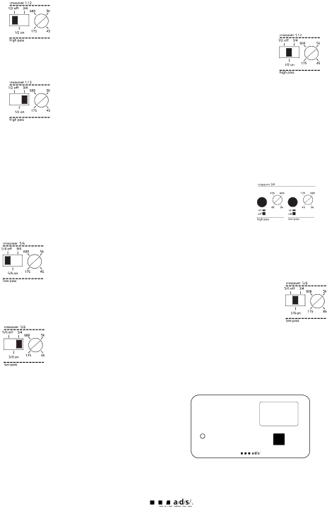
multi-cross™ crossover configuration
xover control 1/2- The crossover selection for channels 1 & 2 has three options:
When the switch is in the left position, the crossover section of the amplifier is bypassed. Channels 1 & 2 output is full range.
When the switch is in the center position, channels 1 & 2 are filtered through a 12dB per octave
When the switch is in the right position, channels 1 & 2 receive signal from the crossover output of channels 3 & 4.
Note: When crossover 3/4 output is selected for channels 1/2, the 3/4 level control adjusts the output level for channels 1/2 and 3/4 simultaneously.
xover control 3/4- The crossover sections dedicated for channels 3 & 4 are activated by depressing the switch next to each frequency adjustment control. Both
Note: When using both sections to create a bandpass filter, make sure you have selected a
xover control 5/6- The crossover selection for channels 5 & 6 has three options:
When the switch is in the left position, the crossover section of the amplifier is bypassed. Channels 5 & 6 output is full range.
When the switch is in the center position, channels 5 & 6 are filtered through a 12dB per octave
When the switch is in the right position, channels 5 & 6 receive signal from the crossover output of channels 3 & 4.
Note: When crossover 3/4 output is selected for channels 5/6, the 3/4 level control adjusts the output level for channels 3/4 and 5/6 simultaneously.
digital crossover frequency display
To facilitate quicker system tuning, we have incorporated a digital display that shows the crossover frequency for
![]() ch 1/2 high pass
ch 1/2 high pass
![]() ch 3/4 high pass
ch 3/4 high pass
each crossover section, including the lowpass crossover for the constant bass circuit. Push the select switch to scroll through the different sections, and a blue led will indicate which crossover is currently displayed.
![]() ch 3/4 low pass
ch 3/4 low pass
ch 5/6 low pass
![]() constant bass
constant bass
select
16