TROUBLESHOOTING
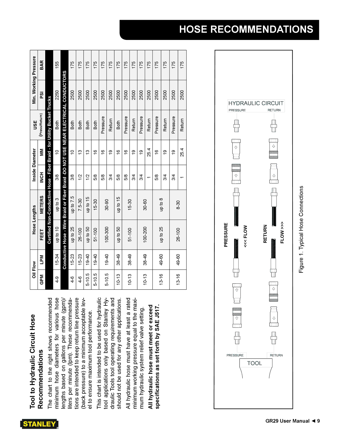
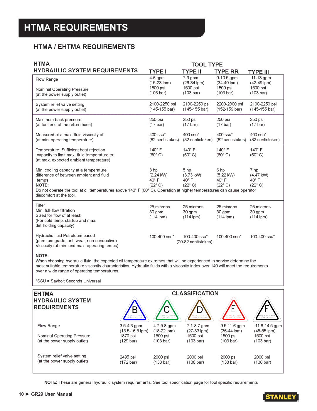
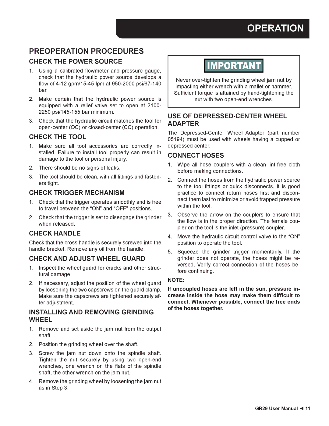
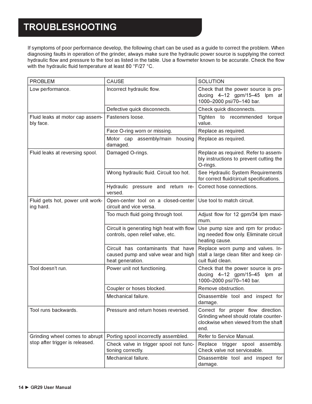
If symptoms of poor performance develop, the following chart can be used as a guide to correct the problem. When diagnosing faults in operation of the grinder, always make sure the hydraulic power source is supplying the correct hydraulic flow and pressure to the tool as listed in the table. Use a flowmeter known to be accurate. Check the flow with the hydraulic fluid temperature at least 80 °F/27 °C.
| PROBLEM | CAUSE | SOLUTION | |
| Low performance. | Incorrect hydraulic flow. | Check that the power source is pro- | |
|
|
| ducing | |
|
|
| ||
|
| Defective quick disconnects. | Check quick disconnects. | |
| Fluid leaks at motor cap assem- | Fasteners loose. | Tighten | to recommended torque |
| bly face. |
| value. |
|
|
| Face | Replace as required. | |
|
| Motor cap assembly/main housing | Replace as required. | |
|
| damaged. |
|
|
| Fluid leaks at reversing spool. | Damaged | Replace as required. Refer to assem- | |
|
|
| bly instructions to prevent cutting the | |
|
|
|
| |
|
| Wrong hydraulic fluid. Circuit too hot. | See Hydraulic System Requirements | |
|
|
| for correct fluid/circuit specifications. | |
|
| Hydraulic pressure and return re- | Correct hose connections. | |
|
| versed. |
|
|
| Fluid gets hot, power unit work- | Use tool to match circuit. | ||
| ing hard. | circuit and vice versa. |
|
|
|
| Too much fluid going through tool. | Adjust flow for 12 gpm/34 lpm maxi- | |
|
|
| mum. |
|
|
| Circuit is generating high heat with flow | Use pump size and rpm for produc- | |
|
| controls, open relief valve, etc. | ing needed flow only. Eliminate circuit | |
|
|
| heating cause. | |
|
| Circuit has contaminants that have | Replace worn pump and valves. In- | |
|
| caused pump and valve wear and high | stall a large clean filter and keep cir- | |
|
| heat generation. | cuit fluid clean. | |
| Tool doesn’t run. | Power unit not functioning. | Check that the power source is pro- | |
|
|
| ducing | |
|
|
| ||
|
| Coupler or hoses blocked. | Remove obstruction. | |
|
| Mechanical failure. | Disassemble tool and inspect for | |
|
|
| damage. |
|
| Tool runs backwards. | Pressure and return hoses reversed. | Correct for proper flow direction. | |
|
|
| Grinding wheel should rotate counter- | |
|
|
| clockwise when viewed from the shaft | |
|
|
| end. |
|
| Grinding wheel comes to abrupt | Porting spool incorrectly assembled. | Refer to Service Manual. | |
| stop after trigger is released. | Check valve in trigger spool not func- | Replace | trigger spool assembly. |
|
| tioning correctly. | Check valve not serviceable. | |
|
| Mechanical failure. | Disassemble tool and inspect for | |
|
|
| damage. |
|
14 ► GR29 User Manual |
|
|
| |
